RF Foundations Revisited with RFDH
A study path from wavelength and electrical length through 50 ohms, transmission lines, reflection, S-parameters, and decibels.
RF · Microwave
My recomputed and redrawn RF study map connecting public RFDH learning pages with my microwave coursework, Cadence screens, and FMCW work.
32 Notes · 17 Redraws
Every linked page includes equations, a recomputed example, two original diagrams, my coursework connection, and the public source pages I read.
RF calculatorsSeries
A study path from wavelength and electrical length through 50 ohms, transmission lines, reflection, S-parameters, and decibels.
Reference planes connect load impedance, reflection, VSWR, the S-matrix, VNA practice, and cascade calculations.
Ten steps from normalization and L/C movement to admittance, line rotation, and single-stub matching.
P1dB, IMD, IP3, and cascaded noise figure are calculated in one signal chain without conflating the metrics.
Amplifiers, oscillators, PLLs, mixers, filters, couplers, isolators, and antennas connected to an FMCW chain.
core
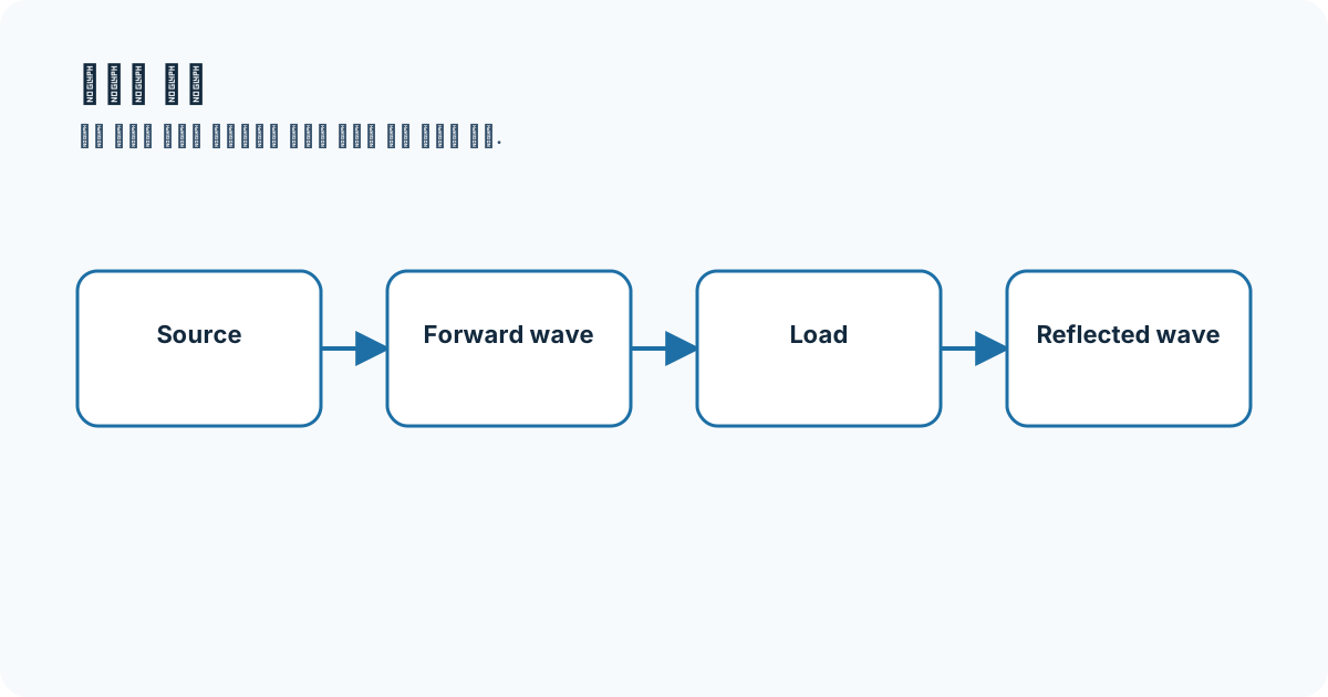
I started by asking why RF is more than a label for high frequency. When physical size is no longer negligible relative to wavelength, phase and reflection must be tracked along position.
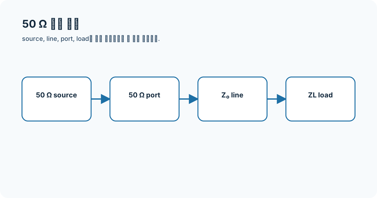
Memorizing 50 ohms, ports, and matching separately made S-parameter setups confusing. I drew the source-line-load reference planes first and connected all three terms on one path.
Instead of listing line names, I compared each structure by return path, field confinement, mode, and fabrication variables.
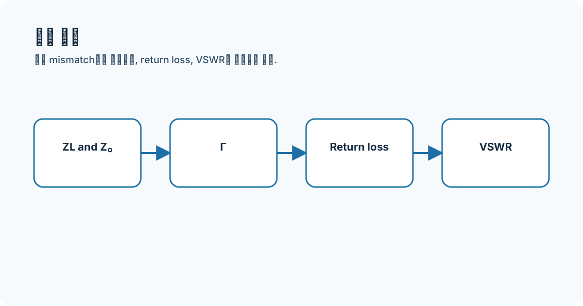
I rewrote the conversion order so that sign conventions and ratios are not mixed when one mismatch is expressed three ways.
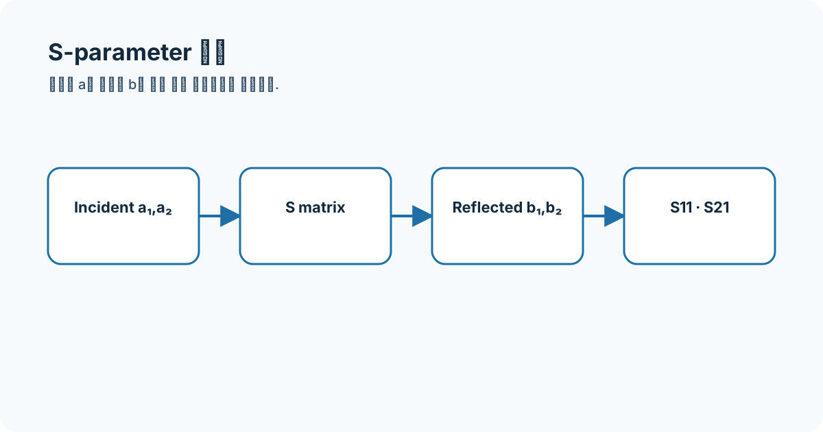
I relabeled S11, S21, S31, and S23 by excitation and observation ports rather than treating them as curve names.
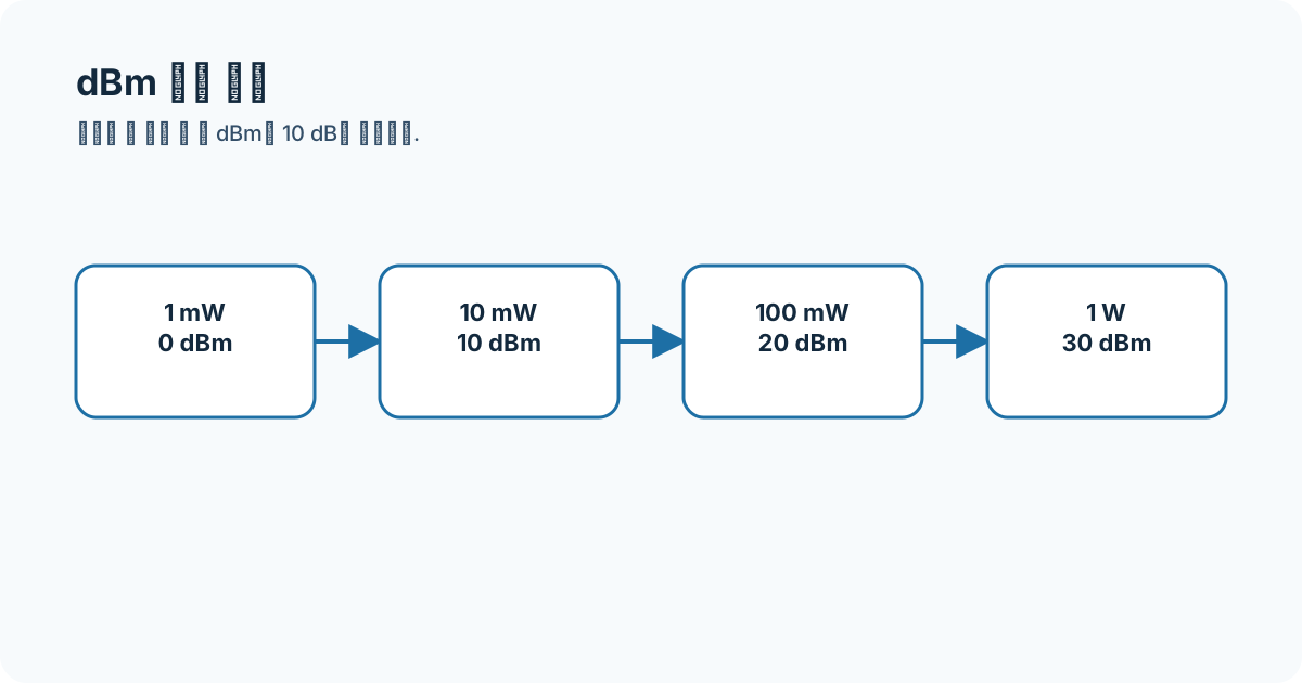
I write the reference and unit first to avoid mixing a dB ratio with absolute dBm power.
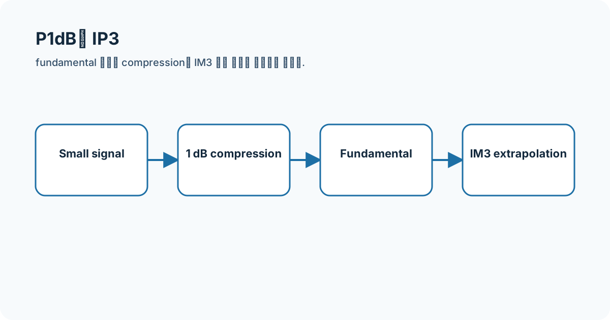
I moved beyond small-signal gain and tracked how fundamentals and distortion change as input level rises.
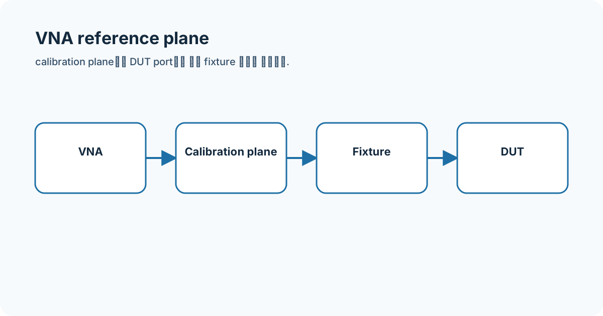
Before placing simulation and instrument results in one table, I drew the calibration plane and fixture boundary.
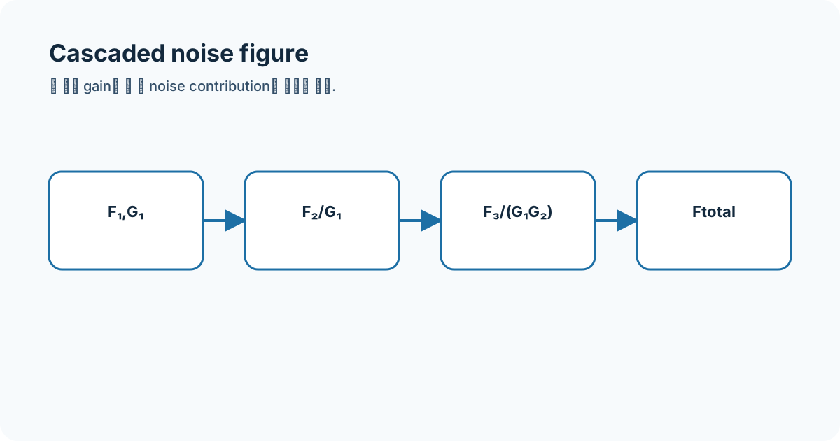
I revisited Friis' equation to see why receiver noise figures cannot simply be added in dB.
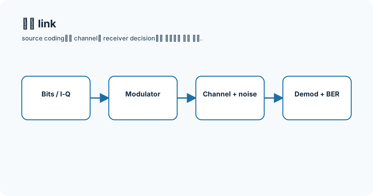
I separated the digital-communications signal flow from the RF front end, then connected baseband I/Q through carrier, channel, and receiver decisions.
I placed RFDH concepts beside my actual Cadence coursework screens and separated design equations, entered geometry, and stored markers.
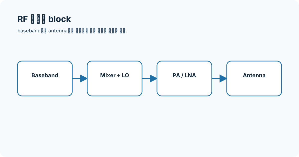
I connected RF-circuit study to FMCW signal processing through chirp generation, transmit/receive chains, mixing, and IF sampling.
smith-chart
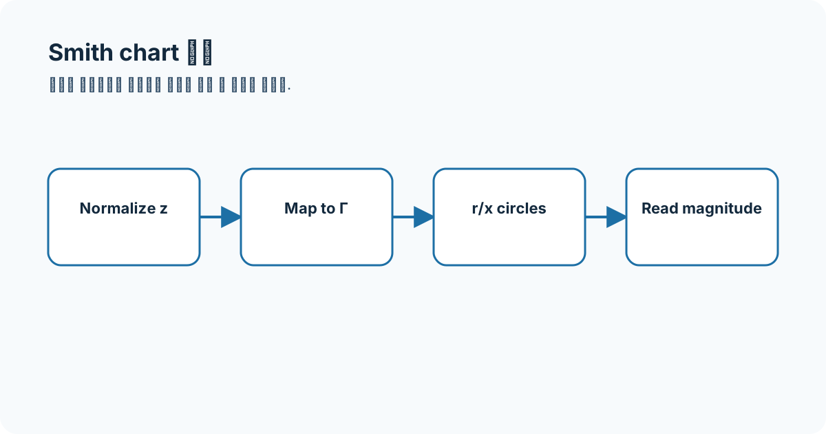
I used the RFDH Smith-chart notes to revisit mapping complex reflection and impedance on one bounded plane with a hand calculation and my own diagram.
I used the RFDH Smith-chart notes to revisit normalizing by reference impedance and restoring ohms with a hand calculation and my own diagram.
I used the RFDH Smith-chart notes to revisit reading intersections of constant-resistance circles and reactance arcs with a hand calculation and my own diagram.
I used the RFDH Smith-chart notes to revisit reading |Γ| and phase from distance and angle with a hand calculation and my own diagram.
I used the RFDH Smith-chart notes to revisit how series reactance moves along a constant-resistance circle with a hand calculation and my own diagram.
I used the RFDH Smith-chart notes to revisit adding parallel elements as susceptance on the admittance chart with a hand calculation and my own diagram.
I used the RFDH Smith-chart notes to revisit using a 180-degree rotation to switch between z and y with a hand calculation and my own diagram.
I used the RFDH Smith-chart notes to revisit how line length rotates phase on a constant-|Γ| circle with a hand calculation and my own diagram.
I used the RFDH Smith-chart notes to revisit finding a g=1 point and cancelling susceptance with a stub with a hand calculation and my own diagram.
I used the RFDH Smith-chart notes to revisit re-reading my stored Smith trajectory by design frequency and component order with a hand calculation and my own diagram.
circuit-blocks
Rather than memorize the whole transceiver, I isolated the inputs, outputs, and role of Amplifiers: Gain, Noise, and Linearity.
Rather than memorize the whole transceiver, I isolated the inputs, outputs, and role of Oscillators and VCOs.
Rather than memorize the whole transceiver, I isolated the inputs, outputs, and role of PLLs and Frequency Synthesis.
Rather than memorize the whole transceiver, I isolated the inputs, outputs, and role of Mixers and IF Selection.
Rather than memorize the whole transceiver, I isolated the inputs, outputs, and role of Frequency Multipliers.
Rather than memorize the whole transceiver, I isolated the inputs, outputs, and role of RF Filters and Prototype Responses.
Rather than memorize the whole transceiver, I isolated the inputs, outputs, and role of Diplexers and Duplexers.
Rather than memorize the whole transceiver, I isolated the inputs, outputs, and role of Couplers, Dividers, and Combiners.
Rather than memorize the whole transceiver, I isolated the inputs, outputs, and role of Isolators and Circulators.
Rather than memorize the whole transceiver, I isolated the inputs, outputs, and role of Reading an Antenna as an RF Port.