RF · Microwave Study
Cascade Noise Figure and First-Stage Gain
I revisited Friis' equation to see why receiver noise figures cannot simply be added in dB.
- Sequence
- 9 / 32
- Track
- core
- Tools
- RF calculators
On this page
Question I started with
I revisited Friis' equation to see why receiver noise figures cannot simply be added in dB.
Connecting the concepts
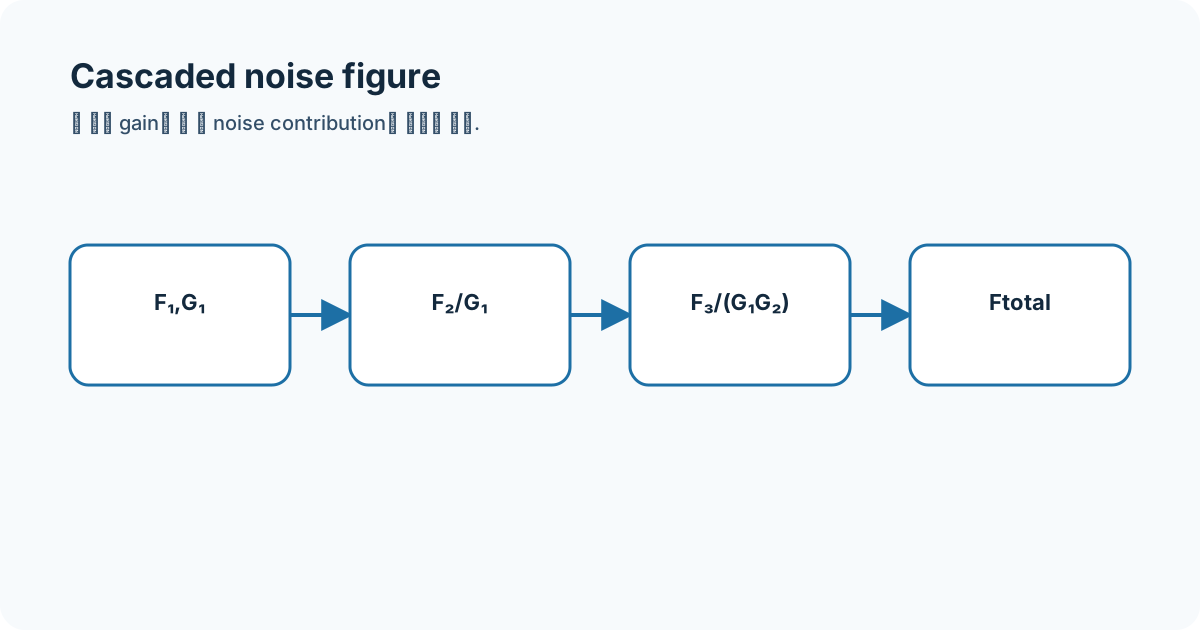
Noise factor F is a linear ratio. In a cascade, later contributions are divided by preceding available gain, which makes first-stage LNA gain and noise figure especially important.
- noise factor
- noise figure
- Friis
- LNA
- available gain
Equations and assumptions
I write the reference impedance, units, and linear-versus-decibel domain before substituting numbers.
F_total = F1 + (F2 - 1)/G1 + (F3 - 1)/(G1 G2)NF_dB = 10 log10(F)Worked example
For NF1=2 dB, G1=15 dB, and NF2=8 dB, linear conversion gives Ftotal≈1.753 and NFtotal≈2.437 dB, not 10 dB.
Connecting it to my coursework and projects
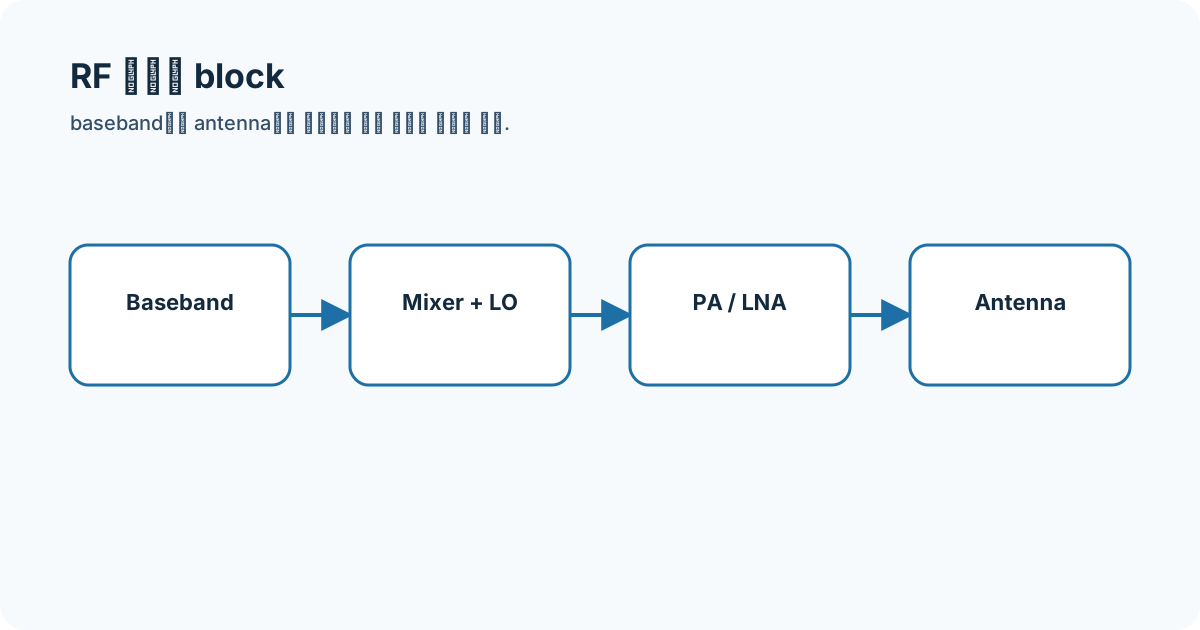
I connect the FMCW receiver order—antenna, LNA, mixer, IF/baseband—to this equation without claiming a measured board noise figure.
High-frequency engineering course hub
What I will check next
Available gain depends on impedance conditions. Calculations that omit passive-loss placement, temperature, and bandwidth are only initial comparisons.