RF · Microwave Study
Recording VNA Calibration and Reference Planes
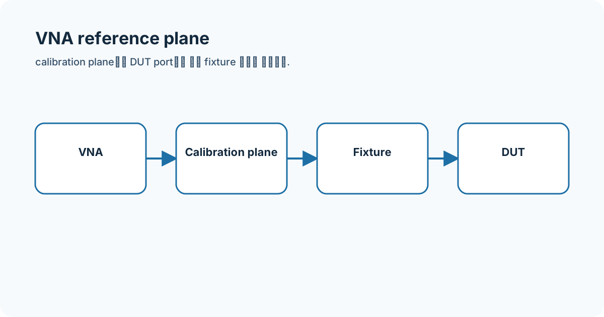
Before placing simulation and instrument results in one table, I drew the calibration plane and fixture boundary.
- Sequence
- 8 / 32
- Track
- core
- Tools
- RF calculators
On this page
Question I started with
Before placing simulation and instrument results in one table, I drew the calibration plane and fixture boundary.
Connecting the concepts
One-port calibration corrects directivity, source match, and reflection tracking; two-port calibration also addresses transmission errors. SOLT and TRL are different methods chosen for the DUT and standards.
- VNA
- SOLT
- TRL
- reference plane
- de-embedding
Equations and assumptions
I write the reference impedance, units, and linear-versus-decibel domain before substituting numbers.
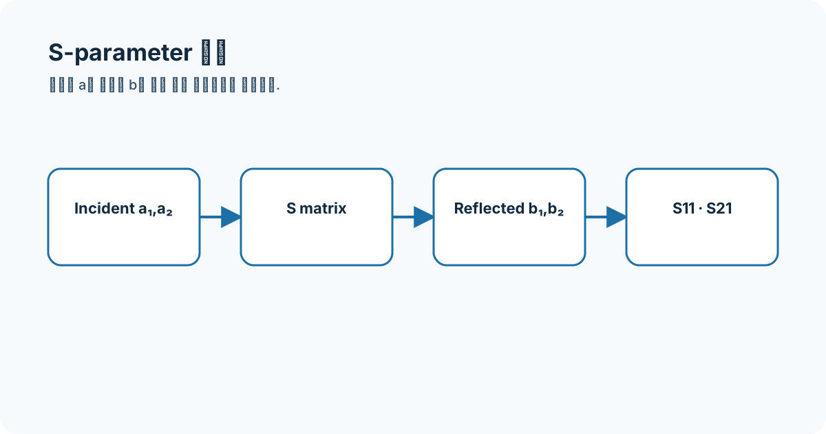
S11 = b1 / a1 at the calibrated planeS21 = b2 / a1 with port 2 matchedWorked example
If a 20 mm fixture remains beyond the calibration plane, its phase and loss appear in the DUT result. Port extension can shift delay but does not remove every mismatch.
Connecting it to my coursework and projects
The published Cadence screens are simulation archives. Without VNA calibration logs, cables, connectors, and fixtures, I do not label them as fabricated-circuit measurements.
High-frequency engineering course hub
What I will check next
Changing sweep points and IF bandwidth changes noise and measurement time. I record original settings rather than smoothing a notch into a better-looking result.