RF · Microwave Study
Converting Reflection Coefficient, Return Loss, and VSWR
I rewrote the conversion order so that sign conventions and ratios are not mixed when one mismatch is expressed three ways.
- Sequence
- 4 / 32
- Track
- core
- Tools
- RF calculators
On this page
Question I started with
I rewrote the conversion order so that sign conventions and ratios are not mixed when one mismatch is expressed three ways.
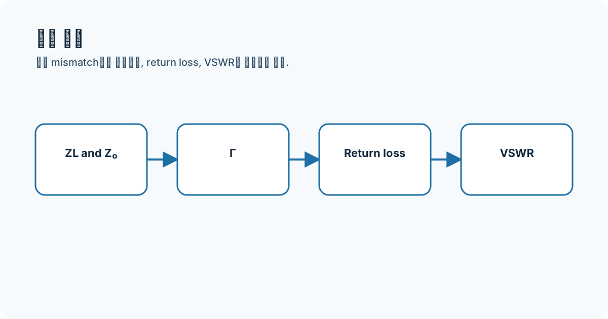
Connecting the concepts
Complex Γ has magnitude and phase; return loss and VSWR use only its magnitude. A negative-dB S11 plot and positive return loss can carry opposite signs, so the displayed definition must be checked.
- Gamma
- return loss
- VSWR
- S11
Equations and assumptions
I write the reference impedance, units, and linear-versus-decibel domain before substituting numbers.
VSWR = (1 + abs(Gamma)) / (1 - abs(Gamma))RL = -20 log10(abs(Gamma))Worked example
For |Γ|=0.2, VSWR=1.5 and return loss is about 13.98 dB; reflected power is 4%. I use 20 log for amplitude ratios and 10 log for power ratios.
Connecting it to my coursework and projects
The saved Wilkinson S11 marker is one matching indicator. Center frequency, other-port terminations, and S23 isolation are also needed to explain the divider.
High-frequency engineering course hub
What I will check next
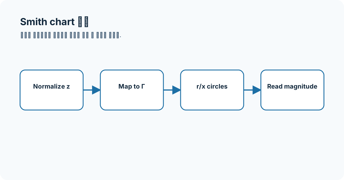
VSWR alone cannot recover reflection phase or mismatch direction; many loads share the same |Γ|, so complex S11 or a Smith chart is needed.