RF · Microwave Study
Comparing Transmission Lines, Microstrip, CPW, Coax, and Waveguide
Instead of listing line names, I compared each structure by return path, field confinement, mode, and fabrication variables.
- Sequence
- 3 / 32
- Track
- core
- Tools
- RF calculators
On this page
Question I started with
Instead of listing line names, I compared each structure by return path, field confinement, mode, and fabrication variables.
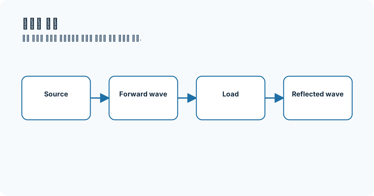
Connecting the concepts
Microstrip spans air and substrate and is commonly treated as quasi-TEM; stripline embeds the conductor in dielectric. CPW keeps grounds on the same plane, while coax and waveguide emphasize TEM behavior and cutoff modes respectively.
- microstrip
- stripline
- CPW
- coax
- waveguide
Equations and assumptions
I write the reference impedance, units, and linear-versus-decibel domain before substituting numbers.
Z_0 = sqrt(L prime / C prime)gamma = alpha + j betaWorked example
A 20 mm lossless line with λg=40 mm is 180 degrees long. If higher effective permittivity reduces λg to 30 mm, the same line becomes 240 degrees.
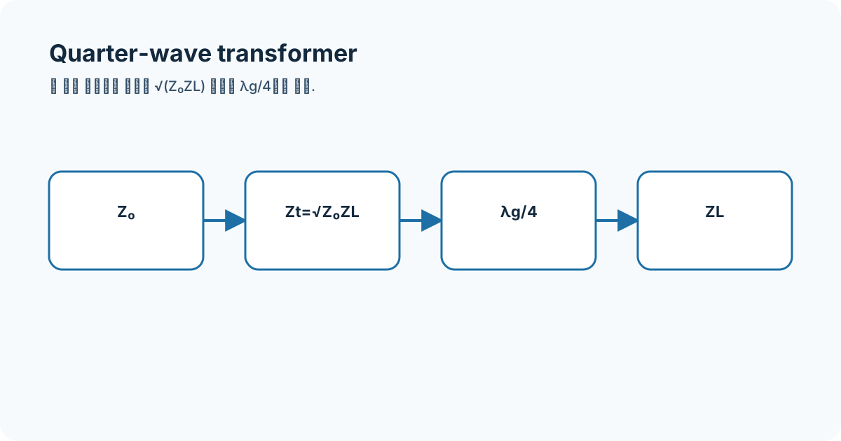
Connecting it to my coursework and projects
The alumina assignment dimensions depend on its stack-up. I do not reuse the stored Cadence W=480 µm and L≈24.9 mm as universal values for another substrate.
High-frequency engineering course hub
What I will check next
Closed-form microstrip equations provide starting values; they do not replace EM or measurement checks including thickness, loss tangent, dispersion, roughness, launches, and tolerance.