RF · Microwave Study
Reading the S-Parameter Matrix and VNA Screens
I relabeled S11, S21, S31, and S23 by excitation and observation ports rather than treating them as curve names.
- Sequence
- 5 / 32
- Track
- core
- Tools
- RF calculators
On this page
Question I started with
I relabeled S11, S21, S31, and S23 by excitation and observation ports rather than treating them as curve names.
Connecting the concepts
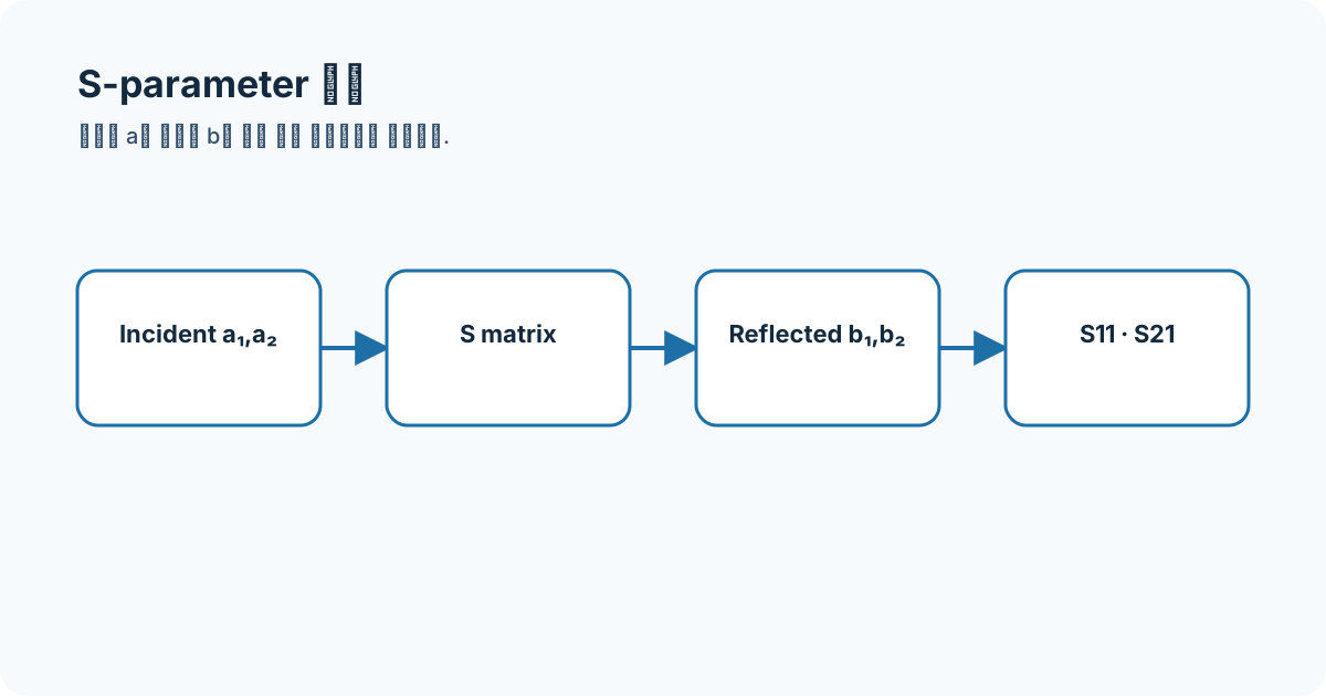
For Sij, index j is the excited port and i is the observed response. Other ports are terminated in the reference impedance, and the matrix separates match, forward/reverse transmission, and isolation.
- S11
- S21
- S31
- isolation
- VNA
Equations and assumptions
I write the reference impedance, units, and linear-versus-decibel domain before substituting numbers.
b = S aS21 = b2 / a1 when all other incident waves are zeroWorked example
Each output of an ideal equal power divider is 3.0103 dB below the input, so |S21|=|S31|≈0.707 and 20log10(0.707)≈−3.01 dB.
Connecting it to my coursework and projects
In my stored Cadence Wilkinson view I read S21/S31 split with S23 isolation. The branch-line amplitude curves alone do not prove 90-degree phase balance.
High-frequency engineering course hub
What I will check next
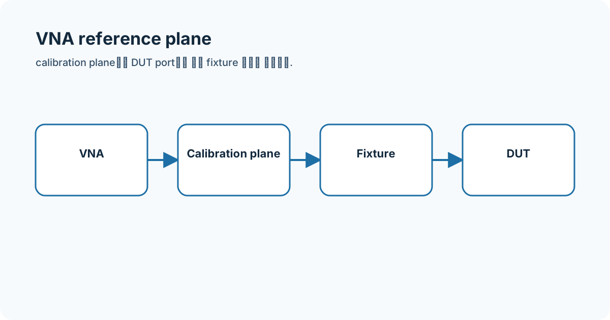
A simulation port is not automatically a calibrated VNA port. Without fixture de-embedding and reference-plane control, a plot is not described as a DUT-terminal measurement.