RF · Microwave Study
Shunt L and C in Admittance
I used the RFDH Smith-chart notes to revisit adding parallel elements as susceptance on the admittance chart with a hand calculation and my own diagram.
- Sequence
- 18 / 32
- Track
- smith-chart
- Tools
- RF calculators
On this page
Question I started with
I used the RFDH Smith-chart notes to revisit adding parallel elements as susceptance on the admittance chart with a hand calculation and my own diagram.
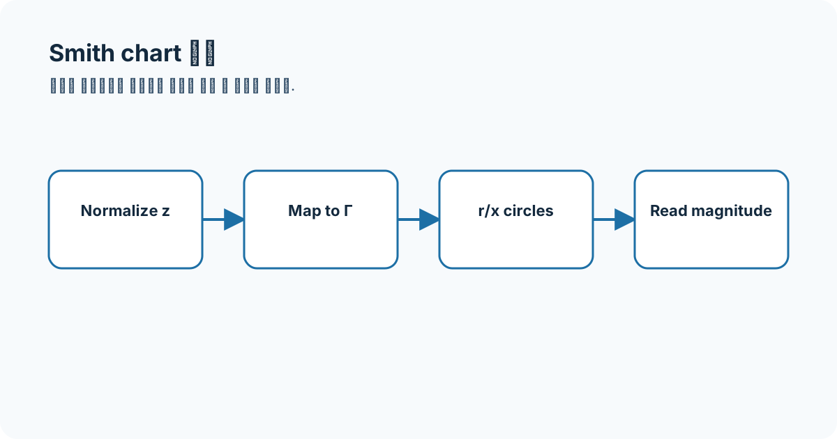
Connecting the concepts
The key is adding parallel elements as susceptance on the admittance chart. Before reading coordinates I record Z0, frequency, and impedance/admittance mode, then label each element or line-length move.
- Smith chart
- normalized impedance
- reflection coefficient
- matching
Equations and assumptions
I write the reference impedance, units, and linear-versus-decibel domain before substituting numbers.
Y = 1/ZB_C = omega CWorked example
At 1 GHz, +j20 mS shunt susceptance is about 3.18 pF.
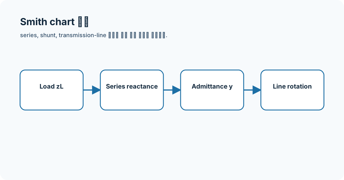
Connecting it to my coursework and projects
I use this order when reading my stored L-section and single-stub screens. The trajectory is an archived simulation view, not a current rerun.
High-frequency engineering course hub
What I will check next
Visual chart readings may differ slightly from calculated values. A matching answer is incomplete without normalization, wavelength direction, and open/short-stub type.