RF · Microwave Study
From RF Circuits to FMCW Radar Signal Processing
I connected RF-circuit study to FMCW signal processing through chirp generation, transmit/receive chains, mixing, and IF sampling.
- Sequence
- 12 / 32
- Track
- core
- Tools
- RF calculators
On this page
Question I started with
I connected RF-circuit study to FMCW signal processing through chirp generation, transmit/receive chains, mixing, and IF sampling.
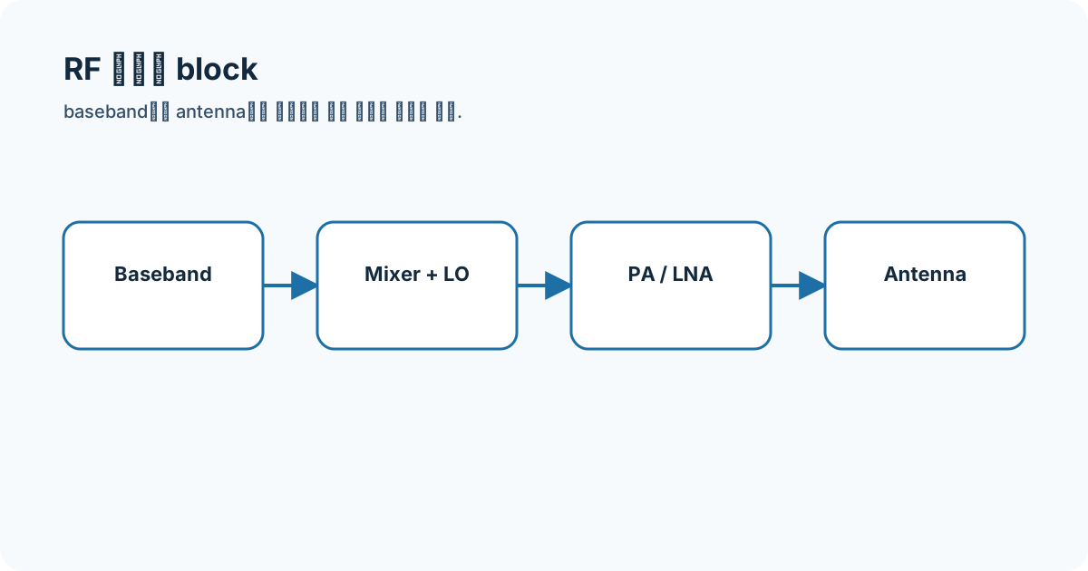
Connecting the concepts
A PLL/VCO creates chirp slope; mixing the transmitted chirp with a delayed echo produces beat frequency. ADC sampling, range FFT, slow-time Doppler, and antenna-phase processing follow as distinct processing stages.
- FMCW
- chirp
- mixer
- beat frequency
- range FFT
Equations and assumptions
I write the reference impedance, units, and linear-versus-decibel domain before substituting numbers.
f_b = S tauR = c f_b / (2 S)Worked example
With slope S=30 MHz/µs and a 2 MHz beat, the ideal range estimate is 10 m. Actual bins and bias depend on sampling, windows, calibration, and leakage.
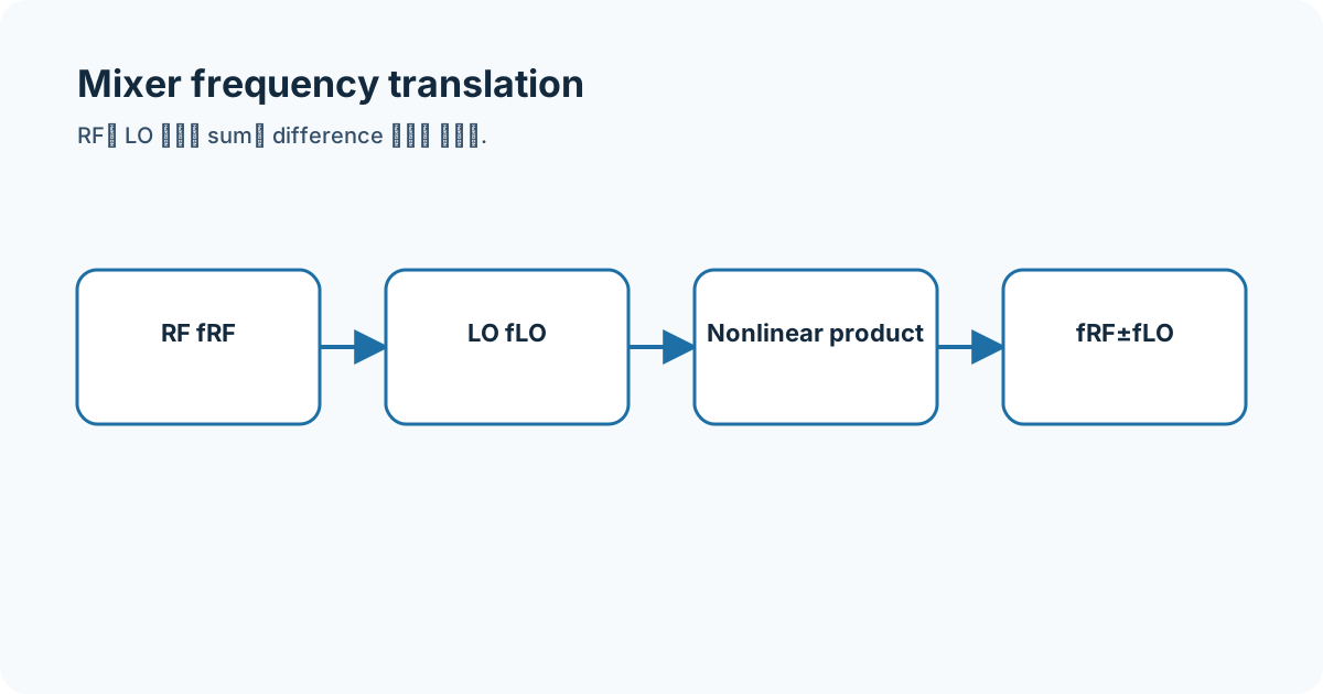
Connecting it to my coursework and projects
My FMCW research page treats ECG, SCG, and radar alignment as a concurrent-signal timing problem and keeps the existing boundary against labeling a valve event from one radar peak alone.
High-frequency engineering course hub
What I will check next
The range equation assumes an ideal linear chirp. A calculation omitting antenna pattern, multipath, phase noise, nonlinearity, motion, and processing choices is not a people-tracking performance result.