RF · Microwave Study
PLLs and Frequency Synthesis
Rather than memorize the whole transceiver, I isolated the inputs, outputs, and role of PLLs and Frequency Synthesis.
- Sequence
- 25 / 32
- Track
- circuit-blocks
- Tools
- RF calculators
On this page
Question I started with
Rather than memorize the whole transceiver, I isolated the inputs, outputs, and role of PLLs and Frequency Synthesis.
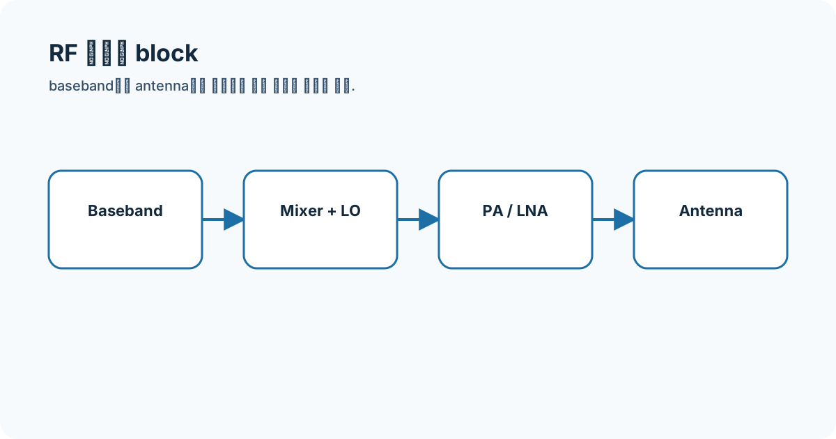
Connecting the concepts
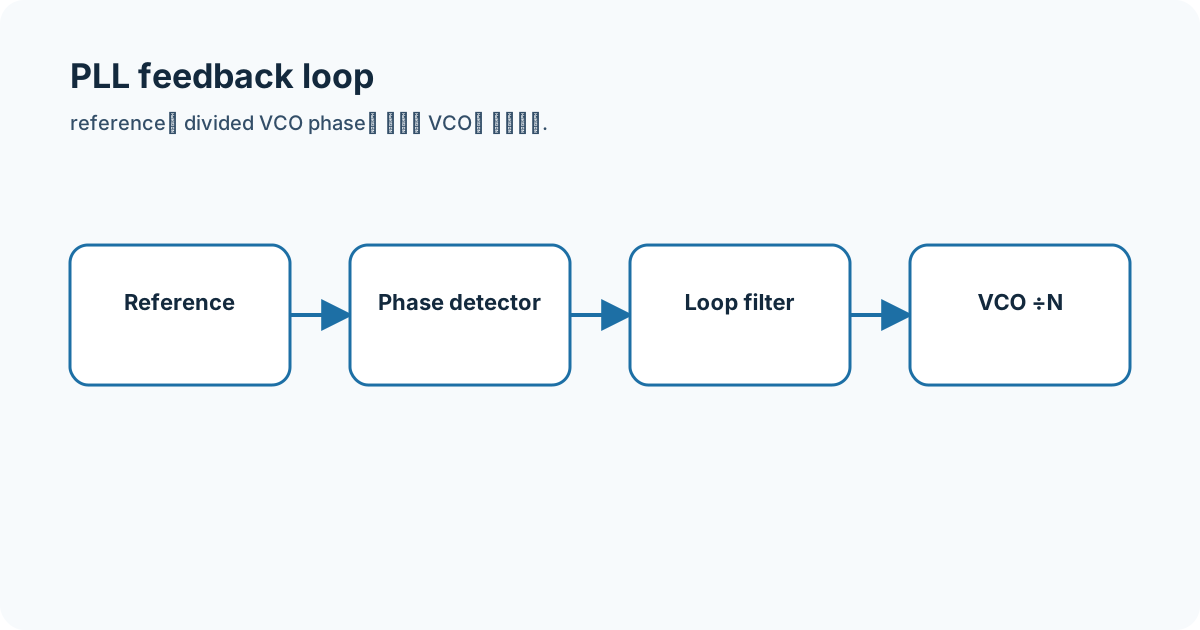
The key is the phase detector, loop filter, VCO, and divider form one feedback loop. Frequency, impedance, gain/loss, noise, and linearity at both sides are recorded before connecting the block.
- PLLs
- RF block
- S-parameter
- signal chain
Equations and assumptions
I write the reference impedance, units, and linear-versus-decibel domain before substituting numbers.
f_out = N f_refomega_n and damping set loop dynamicsWorked example
With fref=10 MHz and N=240, ideal fout=2.4 GHz.
Connecting it to my coursework and projects
I connect this block to my passive-network coursework and FMCW transceiver flow. The example is a recomputed study value, not a hardware measurement.
High-frequency engineering course hub
What I will check next
I do not mix typical, guaranteed, and simulated conditions or directly compare values taken at different frequency, bias, temperature, power, or terminations.