RF · Microwave Study
Couplers, Dividers, and Combiners
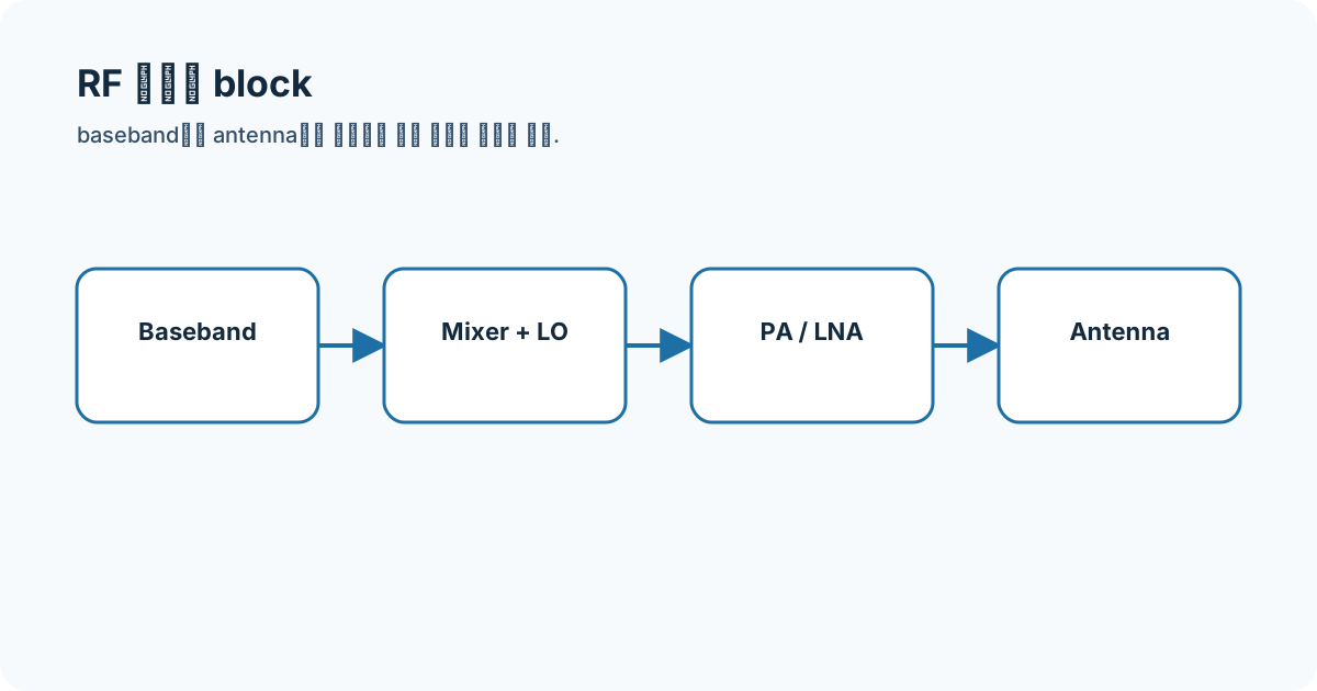
Rather than memorize the whole transceiver, I isolated the inputs, outputs, and role of Couplers, Dividers, and Combiners.
- Sequence
- 30 / 32
- Track
- circuit-blocks
- Tools
- RF calculators
On this page
Question I started with
Rather than memorize the whole transceiver, I isolated the inputs, outputs, and role of Couplers, Dividers, and Combiners.
Connecting the concepts
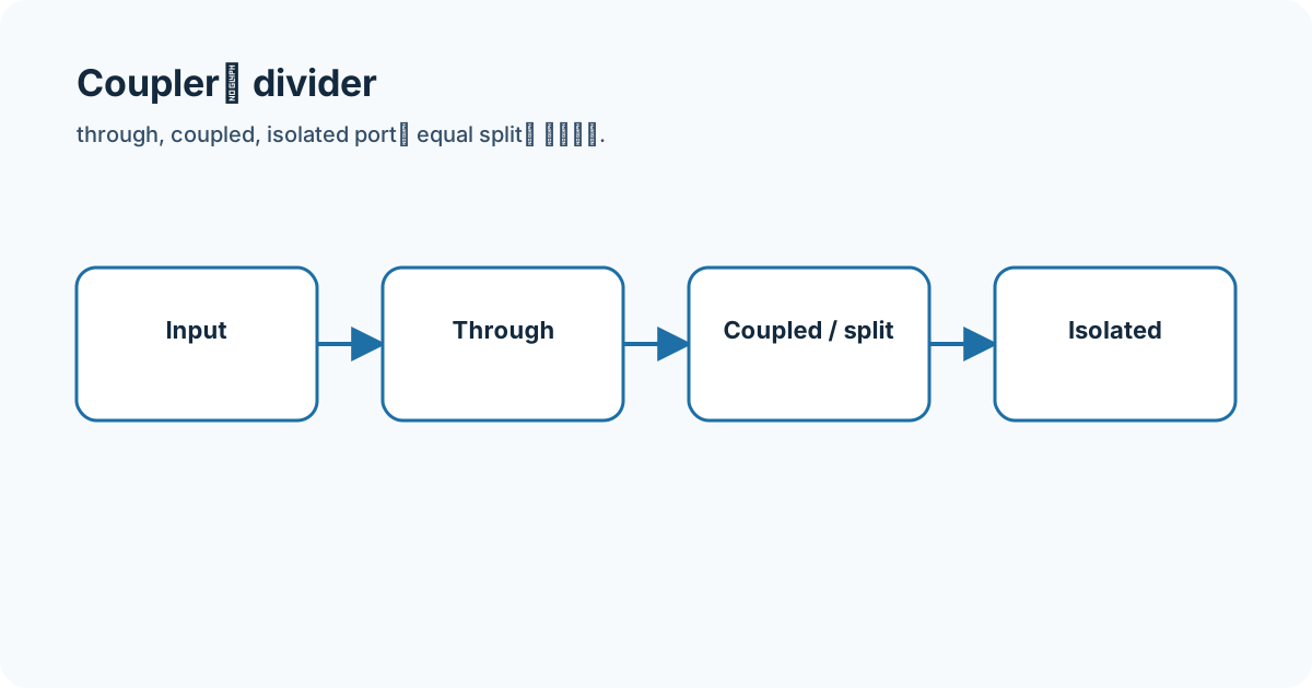
The key is separating through, coupled, isolated, and split ports with S-parameters. Frequency, impedance, gain/loss, noise, and linearity at both sides are recorded before connecting the block.
- Couplers,
- RF block
- S-parameter
- signal chain
Equations and assumptions
I write the reference impedance, units, and linear-versus-decibel domain before substituting numbers.
C_dB = -20 log10(abs(S31))D_dB = Isolation_dB - Coupling_dBWorked example
An ideal equal split is −3.0103 dB per output; dissipative loss is separate.
Connecting it to my coursework and projects
I connect this block to my passive-network coursework and FMCW transceiver flow. The example is a recomputed study value, not a hardware measurement.
High-frequency engineering course hub
What I will check next
I do not mix typical, guaranteed, and simulated conditions or directly compare values taken at different frequency, bias, temperature, power, or terminations.