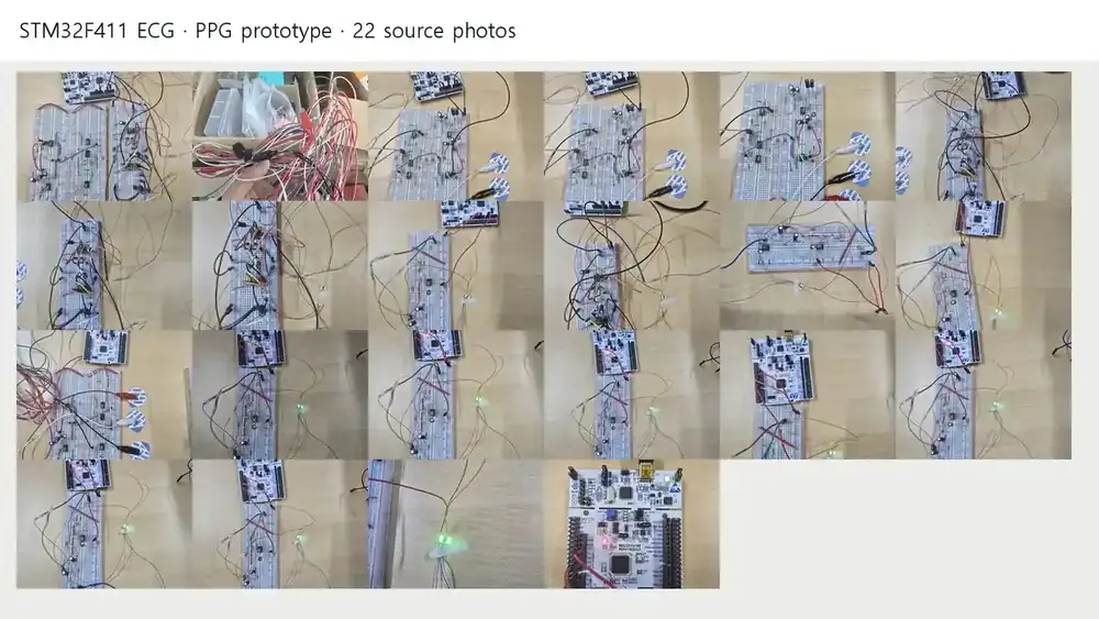
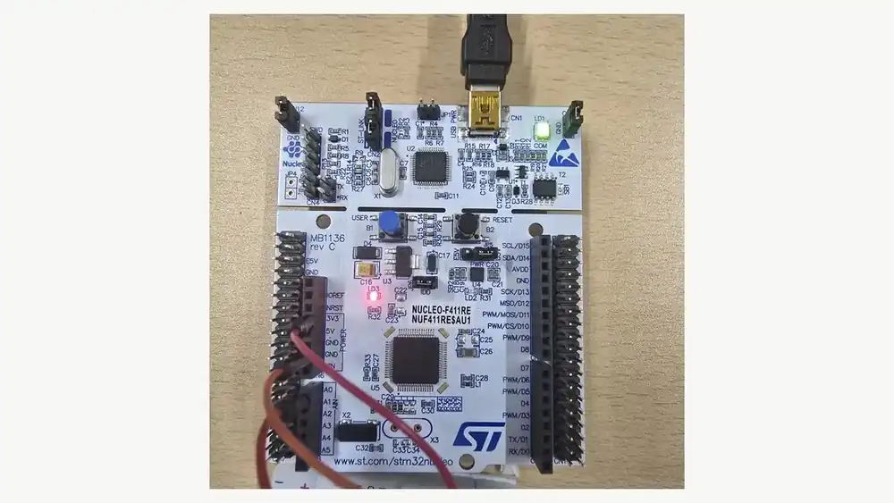
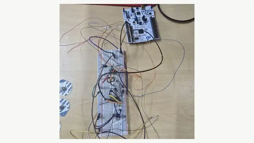
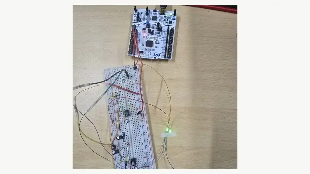
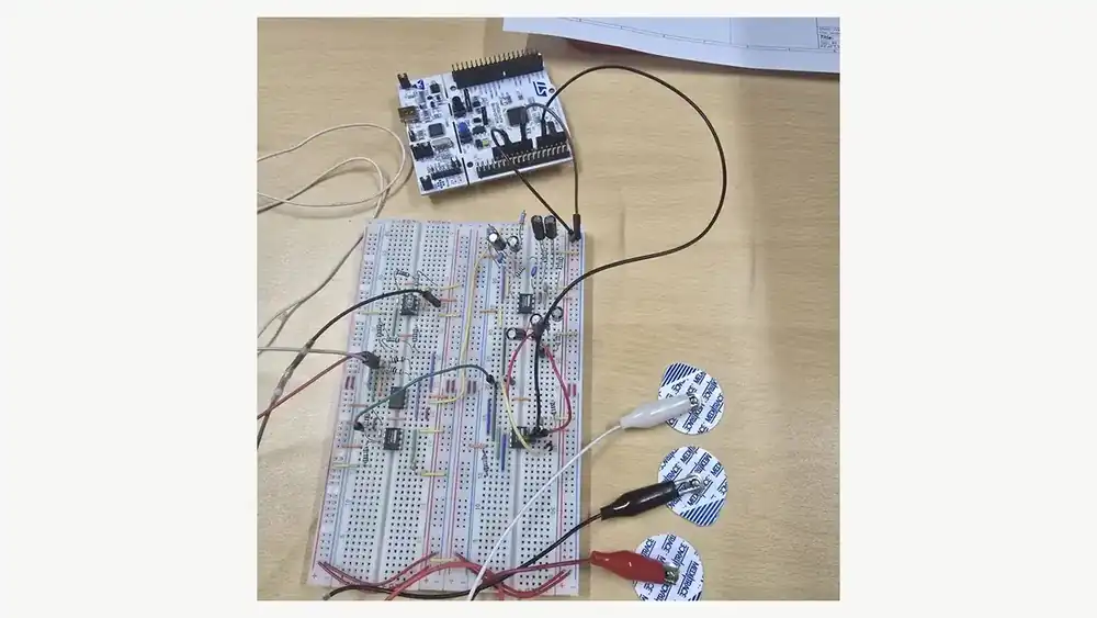
I connect the NUCLEO-F411RE ECG/PPG prototype, CubeIDE setup, ADC/TIM1/UART firmware, CMSIS-DSP biquads, and peak/HRV detection into one study track.
How I selected the material
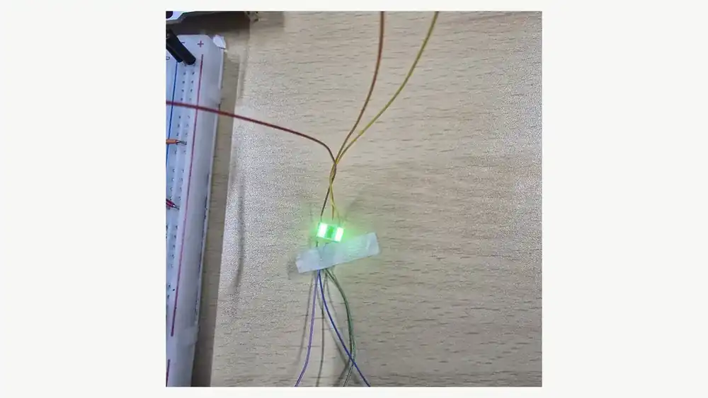
The reviewed sources contain 22 prototype photos, a 40-slide STM setup deck, a three-page KiCad schematic, an ADC/UART note, an HRV module, two PPG code records, twelve top-level ECG C variants, and a complete CubeIDE project archive. I do not count byte-identical variants or ST/Arm vendor files as separate results, and I make no new performance claim without saved measurements.
I first removed PCB-inspection material from the STM32 track, then regrouped the 22 prototype photos, setup slides, schematics, code, and CubeIDE archive by hardware, configuration, acquisition, filtering, and detection.
I retraced project creation, Pinout & Configuration, Clock Configuration, and ADC1/TIM1/USART2 setup from the deck, then checked CMSIS include/source paths, ARM_MATH_CM4, and floating-point printf settings together.
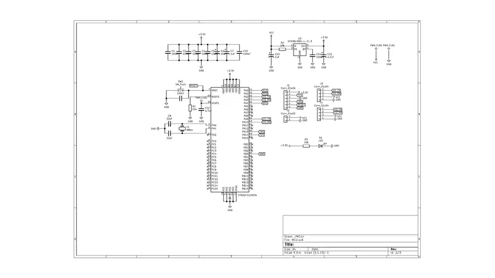
On the KiCad MCU sheet I checked the STM32F411RETx, 3.3 V rail, 8 MHz crystal, reset, SWD, and two UART paths. ECG enters PA0, PPG enters PA1, APG enters PA4, and USART2 uses PA2/PA3.
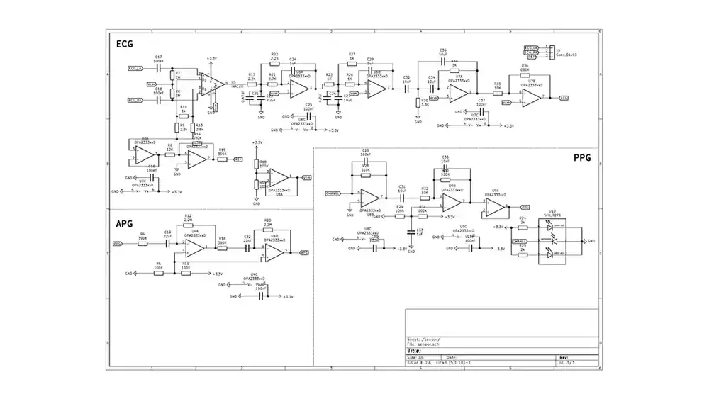
The sensor sheet separates the INA128 ECG input, OPA2333 filter/buffer stages, the SFH7070 PPG sensor, and the Vcm reference. I check analog gain and bias before interpreting ADC codes.
Across the ECG variants, the common structure uses the TIM1 update interrupt as the sample clock and reads ADC1 once. The 250 Hz version transmits sample_index and timestamp_us, applies a five-sample moving average, and then filters the sample.
Using the ADC/UART note, I retraced HAL_ADC_Start, PollForConversion, GetValue, and USART2 transmission. The saved SerialChart configuration uses COM6, 115200 baud, and fields spanning 0-3.3 V and 0-4096 ADC counts.
The 250 Hz ECG sources implement 40 Hz low-pass and 0.5 Hz high-pass stages using DF1 or DF2T cascades. The PPG source instead separates a 0.5 Hz high-pass and 8 Hz low-pass, so I do not reuse ECG coefficients unchanged.
The baseline PPG source runs at 100 Hz and calculates first/second differences and peak intervals. A separate HRV module keeps four peaks, forms three gaps, rejects gaps outside a 20% margin, and then calculates BPM.