STM32 · Embedded · 05
ADC1 and TIM1 Synchronized 250 Hz Sampling
Across the ECG variants, the common structure uses the TIM1 update interrupt as the sample clock and reads ADC1 once. The 250 Hz version transmits sample_index and timestamp_us, applies a five-sample moving average, and then filters the sample.
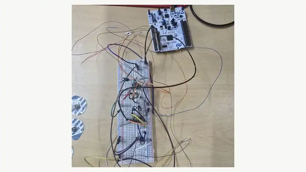
What I checked first
Across the ECG variants, the common structure uses the TIM1 update interrupt as the sample clock and reads ADC1 once. The 250 Hz version transmits sample_index and timestamp_us, applies a five-sample moving average, and then filters the sample.
Source view
- The 12-bit ADC value is converted to voltage with 3.3/4095.
- ADC polling and UART transfer time must be checked against the sampling period.
- The source shows the timing structure, but no saved jitter measurement is available.
Code path
#define ECG_FS_HZ 250U
sample_index++;
HAL_ADC_Start(&hadc1);
ADCValue = HAL_ADC_GetValue(&hadc1);
Smooth_ECG = total / numReadings;
timestamp_us = sample_index * 1000000ULL / ECG_FS_HZ;
Key terms
- TIM1 interrupt
- ADC1
- 250 Hz
- sample index
Review sequence
- TIM1 interrupt
- ADC1 → 250 Hz
- sample index
Official references
- STM32CubeF4 Getting Started (UM1730)
- STM32 DSP with CMSIS (AN4841)
- Arm CMSIS-DSP
- STM32CubeF4 repository
The reviewed sources contain 22 prototype photos, a 40-slide STM setup deck, a three-page KiCad schematic, an ADC/UART note, an HRV module, two PPG code records, twelve top-level ECG C variants, and a complete CubeIDE project archive. I do not count byte-identical variants or ST/Arm vendor files as separate results, and I make no new performance claim without saved measurements.