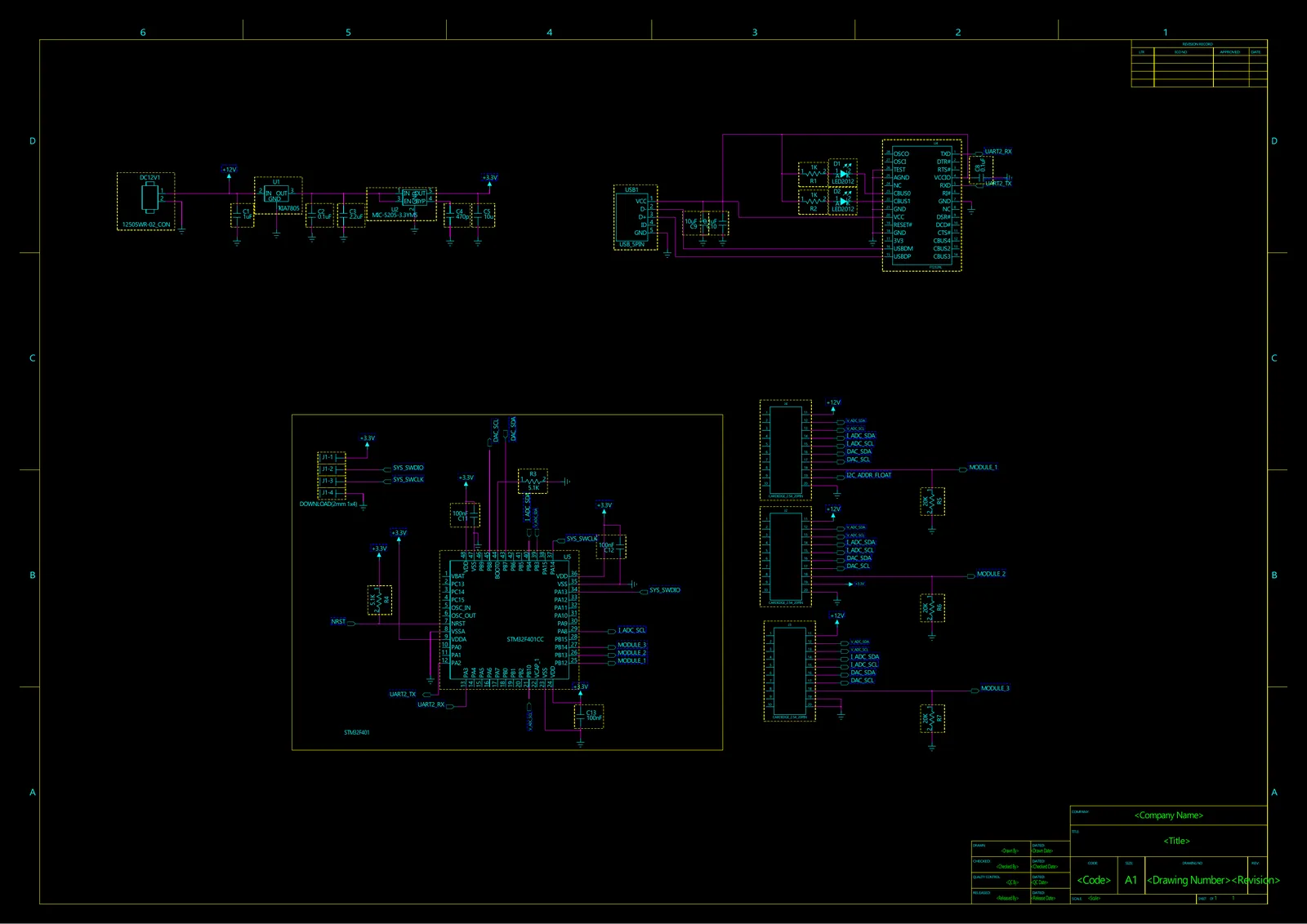
Driving and measuring multiple solar-cell channels requires a clear separation of shared power/reference rails, per-channel current/voltage signal chains, and MCU communication.
02
Architecture
12-V input → 5-V/3.3-V rails → STM32F401 mainboard → three measurement-module connectors → ADC, DAC, op amp, and current sensor → USB/UART.
03
Hardware and Software
STM32F401
PADS Logic
PADS Layout
INA250
AD7997
OPA703
AD5629R
USB UART
04
Data Flow
Cell channel → current/voltage analog path → ADC → MCU → USB/UART, with MCU setpoints → DAC → channel-control path.
05
Methodology
Traced the mainboard and measurement modules by connectors and nets
Decomposed power, reference, ADC, DAC, and amplifier functions into blocks
Compared the stored PADS design with a published MPPT architecture and cited its source
06
Results
Mapped the STM32F401 mainboard and three measurement-module connections
Identified eight-channel current/voltage measurement blocks and ADC/DAC paths
Curated design-source and BOM files for the public archive
Architecture and result views
Measurement-module power conversion, reference, ADC, and connector logicCurrent-sensing signal chain that collects eight channels through one ADCVoltage-control logic that distributes DAC setpoints to per-channel OPA703 pathsKTT0003B PADS decal and pads 1–6 for the LM1084 5-V regulatorSOT95P280X145-6N decal and pin-1 marker for the PI5A124 analog switchMain IC and passive-component BOM snapshot preserved in the design packageReference front layout from the published Kelzenberg, Loke, and Atwater design used for circuit analysis and comparisonBack-side copper and return-path layout of the published reference board
What I worked on
Analyzed 12-V input, 5-V/3.3-V rails, USB/UART, and SWD paths
Decomposed the INA250 current path, AD7997 ADC, OPA703 voltage path, and AD5629R DAC functions
Organized multichannel connector/net flow, BOM, and PCB artifacts
Code and results
STM32F401 mainboard and measurement-module schematic/PCB files
Parts list and PADS schematic
Architecture comparison with a published 12-channel MPPT design
Design scope and next steps
12-channel MPPT reference: Kelzenberg, Loke, and Atwater. Available artifacts: schematics, PCB files, and BOM. Follow-up measurements: accuracy, efficiency, and thermal characteristics.
The STM32F401 mainboard records cover its 12-V input, 5-V/3.3-V rails, USB/UART, and measurement-module connectors. The module separates eight-channel current sensing, ADC, voltage amplification, and DAC paths.