Embedded Systems · Edge Sensing

Real-Time Drowsiness Monitor

Integrates PPG and EAR vision across a two-node Raspberry Pi sensing/analysis architecture with TCP/IP and GPIO/I²C alarm paths.

Source code and physical prototype
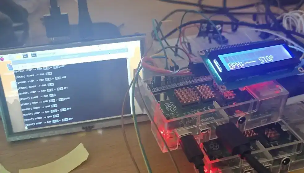
Drowsiness-monitoring prototype built with Raspberry Pi boards, an LCD, and sensor wiring

01

Problem

The project acquires and analyzes PPG and camera-based EAR signals across two Raspberry Pi nodes and integrates the resulting alarm path.

02

Architecture

A PPG sensing node and an image/EAR analysis node communicate through TCP/IP and file IPC, with GPIO/I²C driving LCD and alarm outputs.

03

Hardware and Software

  • Raspberry Pi
  • C/C++
  • OpenCV
  • TCP/IP
  • GPIO
  • I²C
  • LCD

04

Data Flow

PPG/camera sensing → per-node preprocessing → network/file IPC → fatigue-decision path → LCD/alarm output.

05

Methodology

  • Integrated PPG-server and image/EAR-processing modules
  • Documented two-node communication and state transfer
  • Documented the LCD/alarm interfaces and prototype wiring

06

Results

  • Two-node architecture implemented in the C/C++ source
  • Data and alarm paths connected through TCP/IP, GPIO, and I²C
  • LCD and sensor wiring shown in the original prototype photographs
01Problem

The project acquires and analyzes PPG and camera-based EAR signals across two Raspberry Pi nodes and integrates the result...

02Architecture

A PPG sensing node and an image/EAR analysis node communicate through TCP/IP and file IPC, with GPIO/I²C driving LCD and a...

03Method

Integrated PPG-server and image/EAR-processing modules

04Result

Two-node architecture implemented in the C/C++ source

A compact problem-to-result map generated from the project data used on this page.

What I worked on

  • PPG server and image/EAR processing
  • Two-node file IPC and network architecture
  • Documentation of the LCD and alarm integration path

Code and results

  • C/C++ source and architecture documentation
  • Circuit, LCD, and prototype photographs
  • TCP/IP, GPIO, and I²C data and alarm paths

Next steps

Next, I plan to measure latency, sensitivity, specificity, and false-alarm rate under one consistent test setup.

Prototype photographs show that the integration path existed, but they do not substitute for accuracy, latency, sensitivity, or false-alarm measurements.

Publication first-page preview