Sensing server
PPG front end, 12-bit ADC, HPF/LPF, peak/IBI/BPM calculation, and TCP transmission.
Embedded Systems · Edge Vision · Biosignal
A two-Raspberry-Pi embedded prototype that separates stable PPG acquisition from compute-heavy EAR vision, then connects the sensing server to an analysis/alarm client.
01 · Architecture
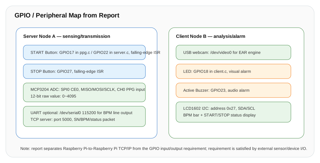
Node A focuses on MCP3204 PPG sampling and BPM packets. Node B combines webcam EAR, file IPC, LCD, LED, and buzzer control, reducing interference between acquisition timing and vision processing.
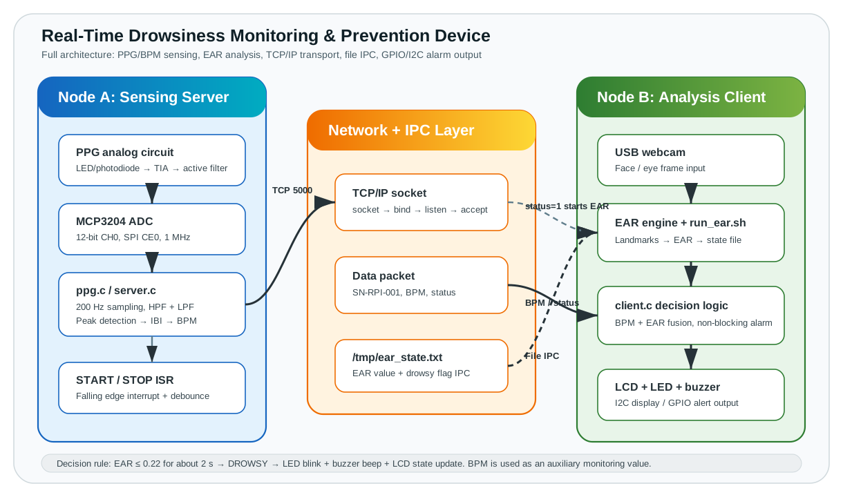
PPG front end, 12-bit ADC, HPF/LPF, peak/IBI/BPM calculation, and TCP transmission.
Reads webcam EAR state and BPM packets, updates the LCD, and makes the drowsiness decision.
Timer-based LED and active-buzzer toggling avoids unnecessary blocking of communication and UI paths.
02 · Dual Signal Path
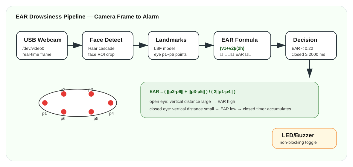
BPM is an auxiliary display value. The primary drowsiness condition is EAR below 0.22 for approximately two seconds—a role boundary preserved in both code and documentation.
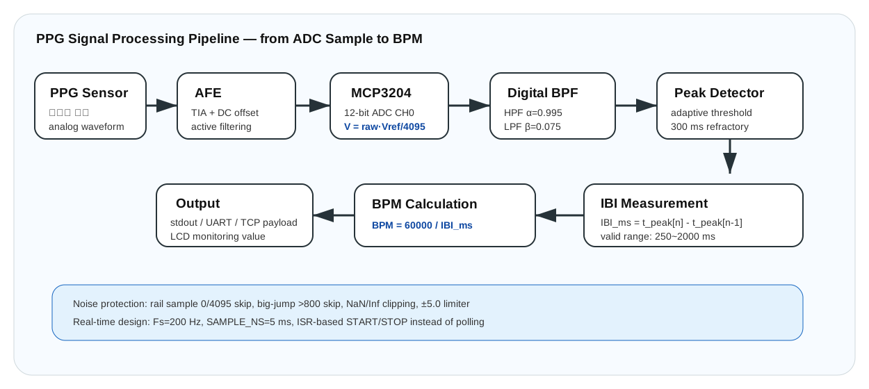
First-order HPF/LPF filtering precedes adaptive peak and refractory conditions.
The geometric ratio falls with closure; a duration rule avoids treating a momentary crossing as drowsiness.
03 · Communication
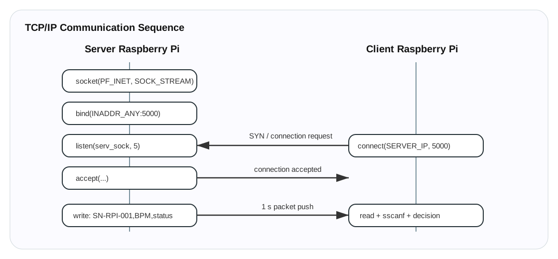
Node A sends SN-RPI-001,BPM,status over TCP port 5000. The EAR engine shares state with the C client through /tmp/ear_state.txt.
04 · Prototype Evidence
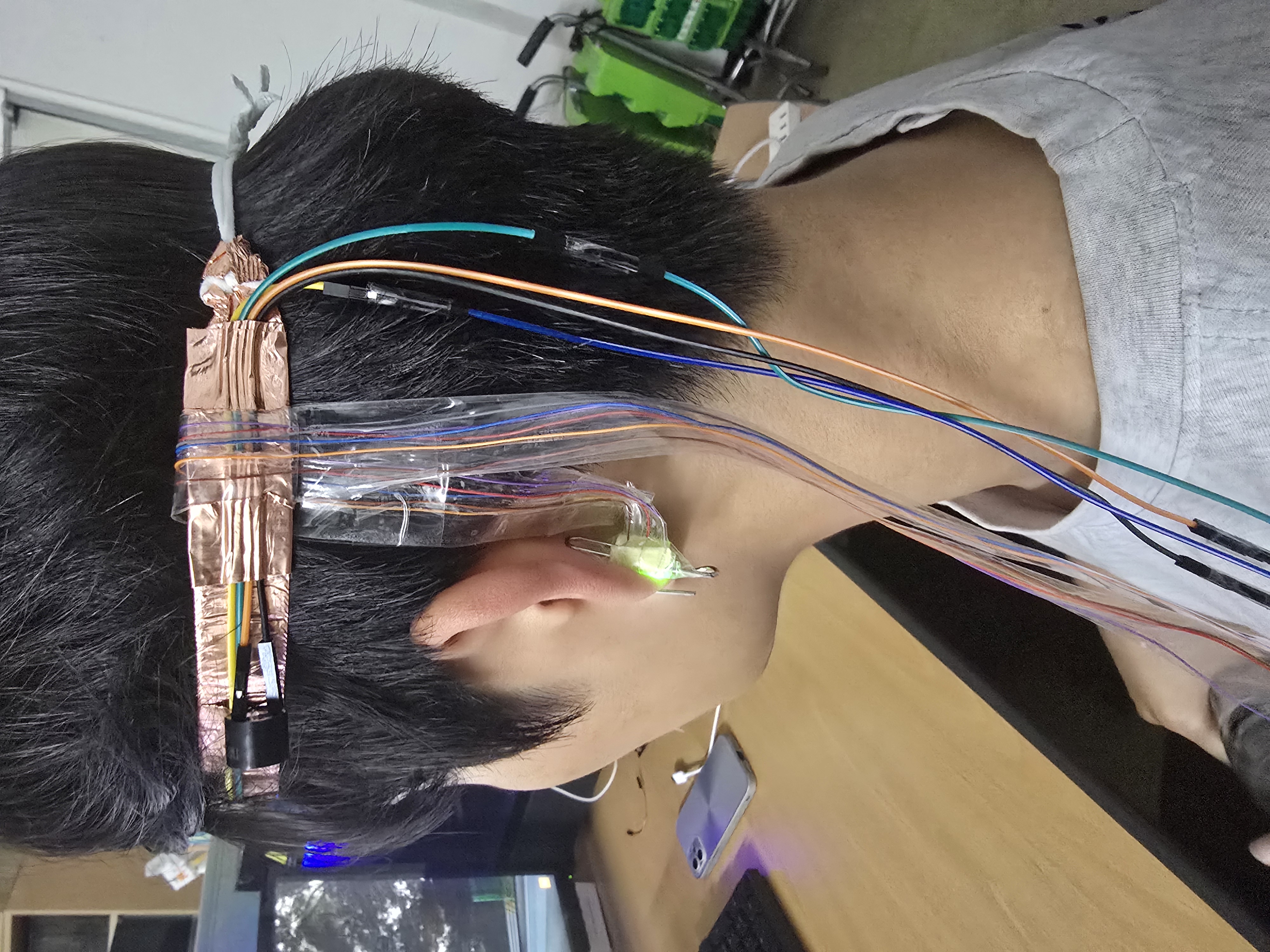
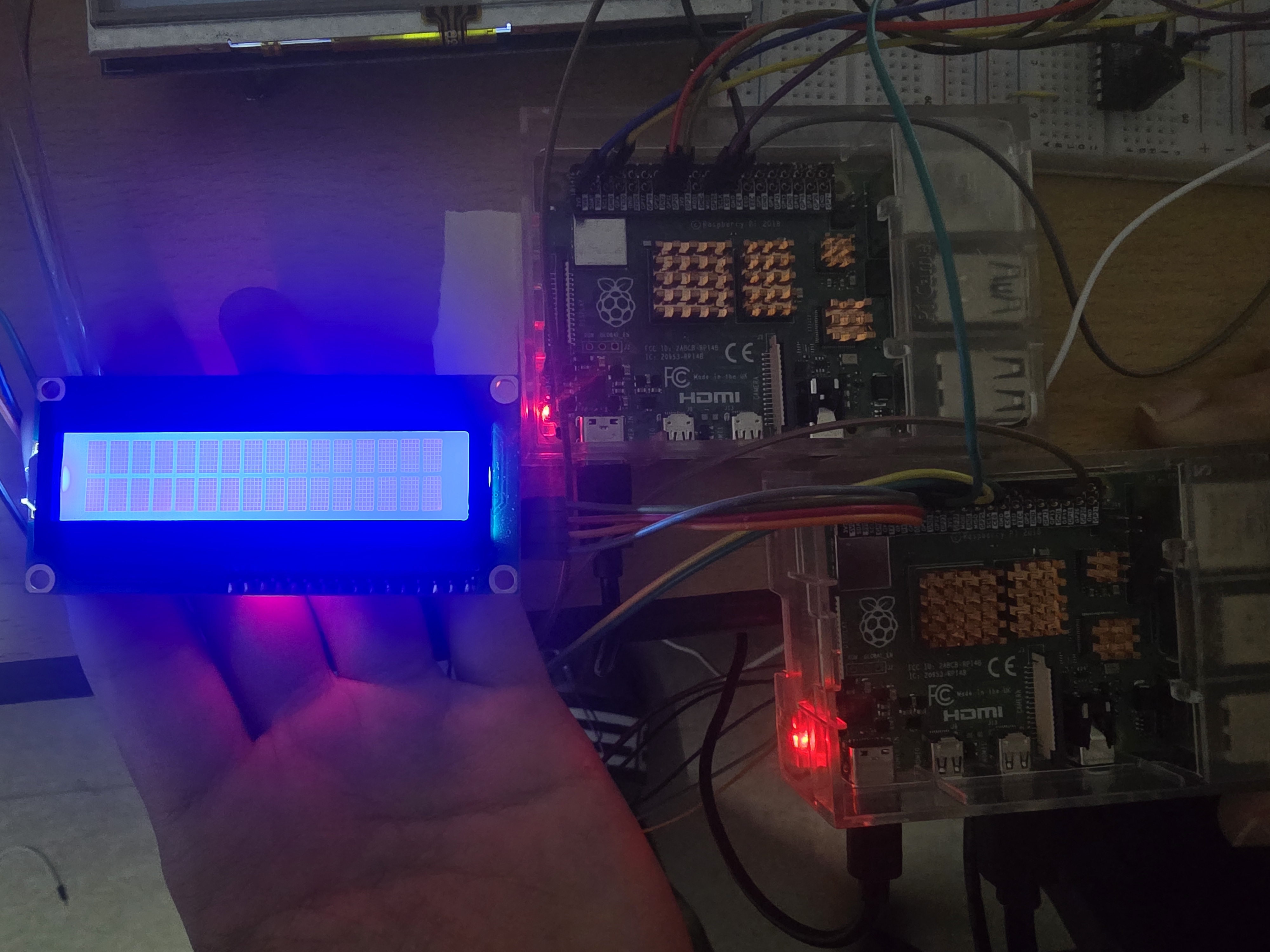
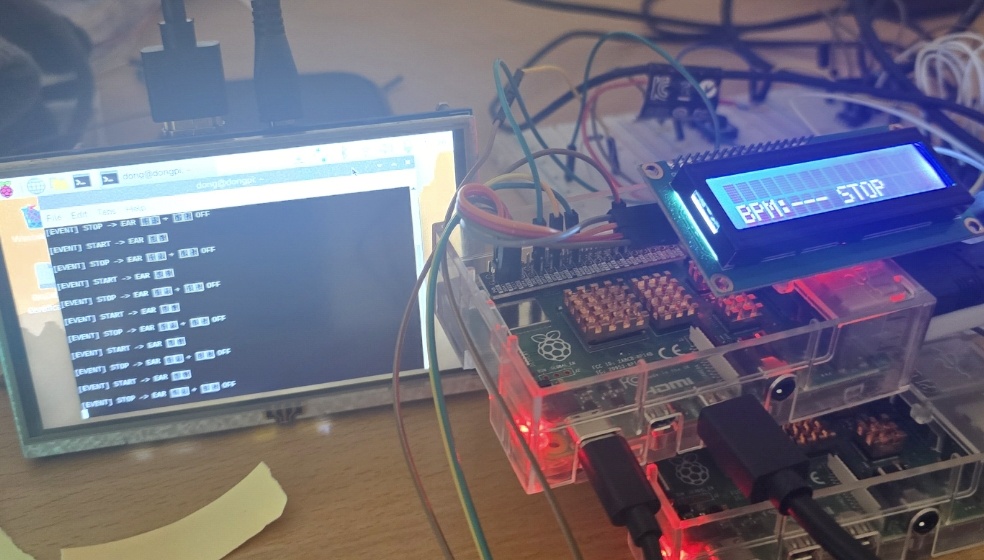
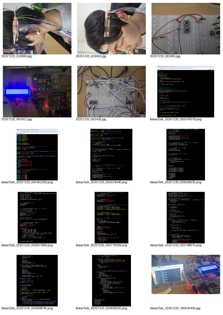
Repository photographs document the circuit, wearable sensor, Raspberry Pi, LCD, code, and demonstration. No public latency, sensitivity, or specificity dataset is present, so this page does not claim numerical performance.
| Validation axis | Current evidence | Interpretation |
|---|---|---|
| Circuit and mechanics | Photo evidence | Wearable, PPG circuit, and RPi/LCD photographs |
| Software structure | Source documented | C/C++/Bash, TCP, IPC, and GPIO paths included |
| Numerical performance | Not reported | No public latency, sensitivity, or specificity table |
| Product/safety certification | Prototype only | Not a certified driver-safety or medical device |