Week 08
DC-DC Converter Control
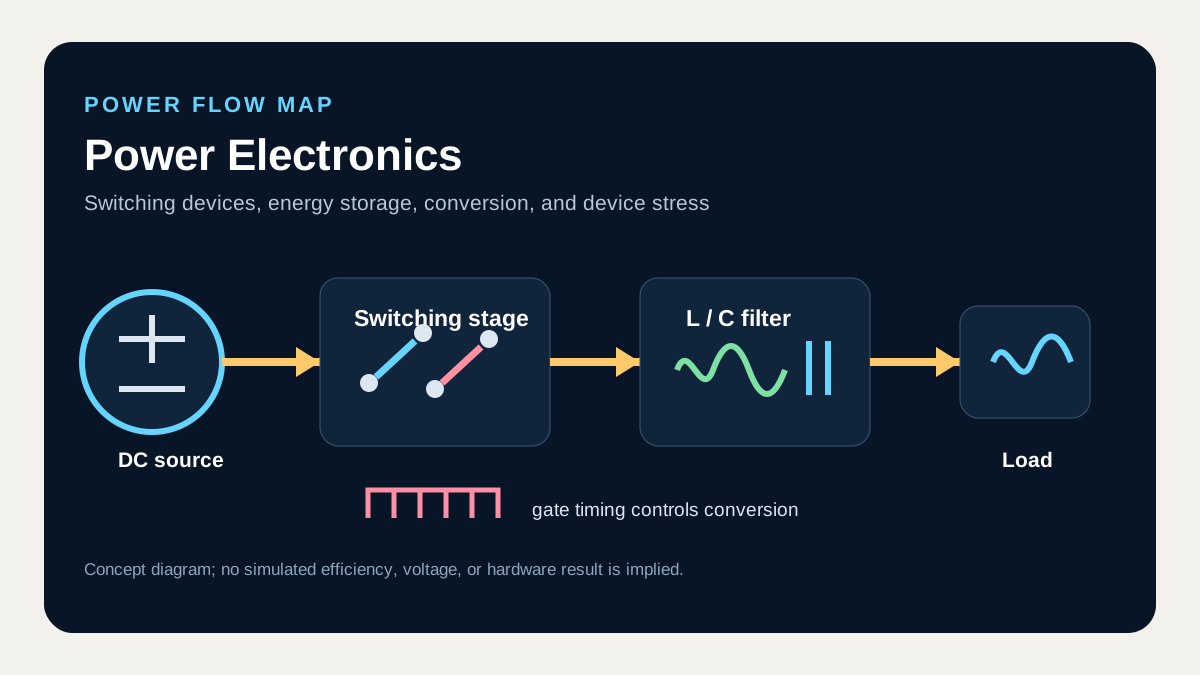
I organize a study path from switching devices to converters and inverters while tracking power flow and device stress together.
What I connect in this unit
A small-signal model linearizes how a small duty perturbation around an operating point reaches the output. Voltage-mode control drives duty from voltage error, current-mode control adds an inner current ramp that changes plant order and transient behavior, and loop compensation sets crossover and stability margin.
Concept map
- Small-signal models
- Voltage-mode control
- Current-mode control
- Loop compensation
Technical anchor
Use T(s) = G_c(s) G_vd(s) H(s) to read phase margin at the 0 dB crossover, and also examine slope-compensation need when current-mode duty exceeds 0.5.
How I review it
Keep crossover well below switching frequency and verify on one Bode plot that DC accuracy, the output-LC pole, capacitor-ESR zero, and sampling delay meet the same control target.
Connection to the full course
Unit 8 of 12. Unit numbers follow circuit dependencies and do not claim the original lecture schedule.