Week 07
Buck-Boost Converter Families
I organize a study path from switching devices to converters and inverters while tracking power flow and device stress together.
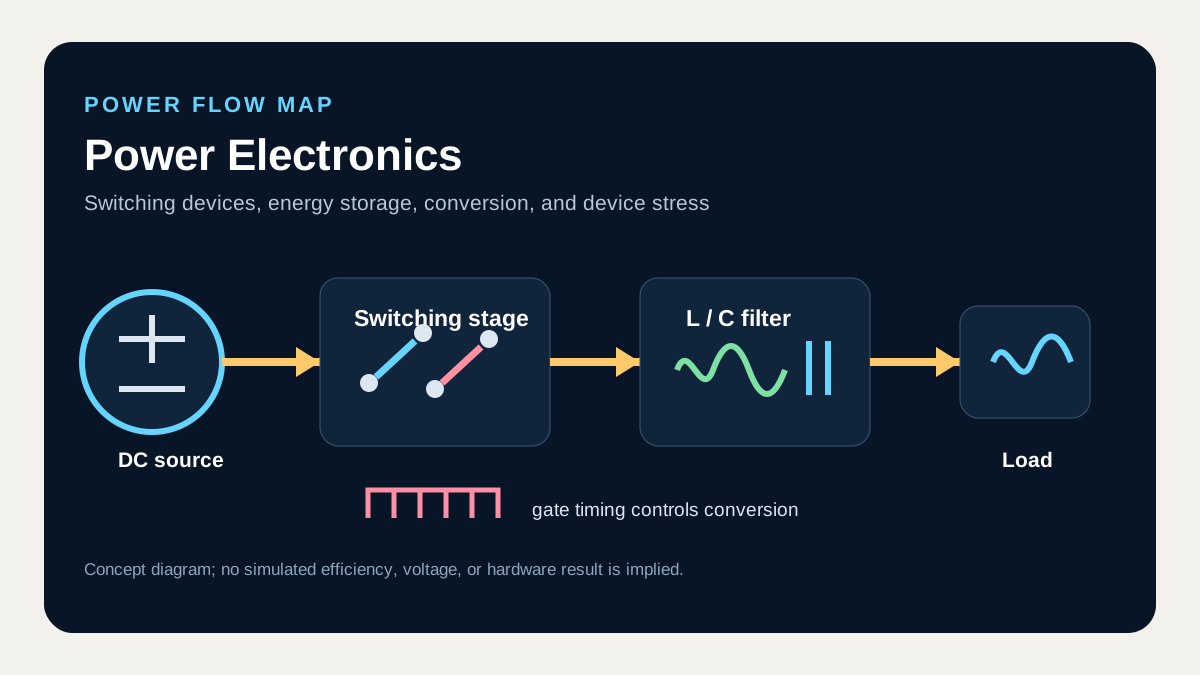
What I connect in this unit
An inverting buck-boost separates energy storage from delivery and reverses output polarity; a flyback extends the same idea with coupled inductance and turns ratio to obtain transformer isolation. Leakage inductance and turns ratio also increase switch and diode stress, so the ideal conversion ratio is not sufficient for design.
Concept map
- Inverting output
- Flyback energy transfer
- Transformer isolation
- Device stress
Technical anchor
The ideal inverting CCM ratio is V_out/V_in = -D/(1-D); a flyback additionally scales this relation by the secondary-to-primary turns ratio.
How I review it
Put dot polarity, on/off current paths, core reset, and the leakage-energy clamp on one schematic, then check flux and device stress at worst-case duty.
Connection to the full course
Unit 7 of 12. Unit numbers follow circuit dependencies and do not claim the original lecture schedule.