Week 09
Single-Phase Inverters
I organize a study path from switching devices to converters and inverters while tracking power flow and device stress together.
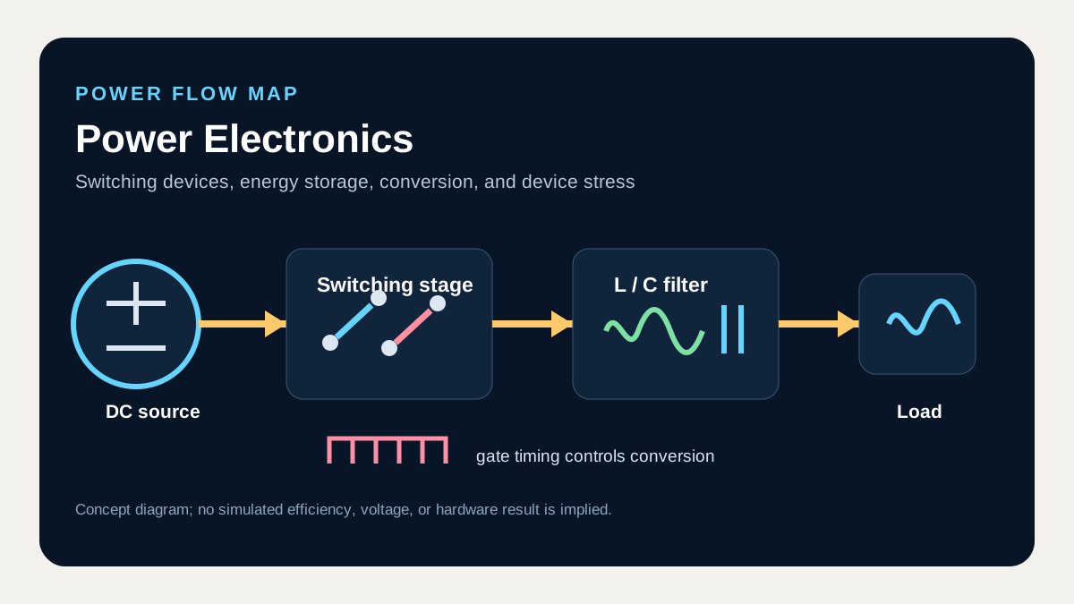
What I connect in this unit
A half bridge produces two voltage levels around the split DC-link midpoint, while a full bridge changes output polarity through the difference between two legs. Bipolar PWM switches directly between +Vdc and -Vdc; unipolar PWM also uses zero states, changing effective ripple frequency and common-mode behavior.
Concept map
- Half bridges
- Full bridges
- Bipolar PWM
- Unipolar PWM
Technical anchor
Full-bridge load voltage is v_ab = v_aN - v_bN, and within the linear sinusoidal-PWM range the fundamental component scales with modulation index.
How I review it
Draw both leg-gate waveforms beside v_ab and compare shoot-through exclusion, zero states, the fundamental, and switching sidebands for bipolar and unipolar PWM.
Connection to the full course
Unit 9 of 12. Unit numbers follow circuit dependencies and do not claim the original lecture schedule.