Electrical Engineering Coursework · Controller Logic Design
Reading the Mealy 101 Detector and 8-to-1 MUX Sources
2026-08-01 · updated 2026-08-01 · Hyeongrok Ryu
My source-level review of overlapping 101 transitions and a decoder-based multiplexer from stored VHDL coursework.
- Type / level
- study-note · beginner
- Tools
- VHDL, Vivado
Starting from source
I reopened the stored mealy.vhd, mealy_tb.vhd, and mux_8to1.vhd files from my 2024 coursework. I focused on the entity, architecture, and stimulus that I had written instead of the Vivado cache and generated executables.
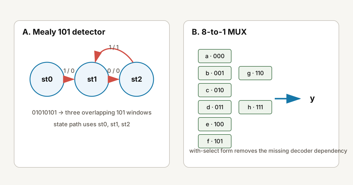
Finding 101 with three states
The transition path uses three states. st0 has no useful prefix, st1 means the latest bit is 1, and st2 means the latest two bits are 10. A 1 in st2 completes 101 and asserts dout. Returning to st1 preserves that final 1 as the start of an overlapping pattern.
| Current state | Input 0 | Input 1 | Output 1 |
|---|---|---|---|
| st0 | st0 | st1 | - |
| st1 | st2 | st1 | - |
| st2 | st2 | st1 | on input 1 |
st2 → st1 transition is the step that keeps overlapping detections possible.Tracing 01010101
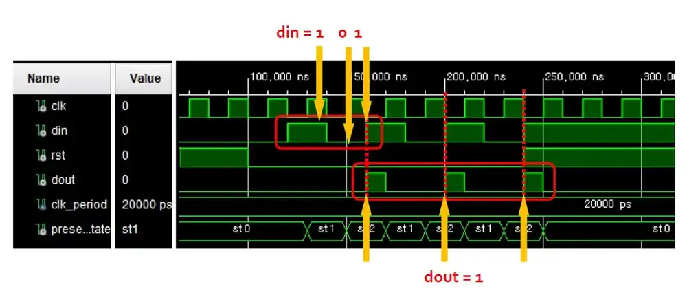
The stored testbench applies 01010101 at 20 ns intervals after reset. The state-transition table predicts 101 detection at the fourth, sixth, and eighth inputs. Result type: source-level hand calculation.
Writing a standalone MUX
The original mux_8to1.vhd instantiates a dec_3to8 component and combines decoded lines with AND and OR gates. The decoder source was not present in the stored bundle I reviewed. I therefore rewrote the same truth table as a dependency-free study example.
with sel select
  y <= a when "000",
       b when "001",
       c when "010",
       d when "011",
       e when "100",
       f when "101",
       g when "110",
h when others;What I will check next
On the next run I will place present_state, next_state, and dout beside the input at each clock edge. For the MUX, I will exercise all select values on the standalone version first and compare the structural version only after recovering its decoder source.
Previous and next
Sources used
- Controller Logic coursework VHDL source — local-coursework; state transitions and source structure