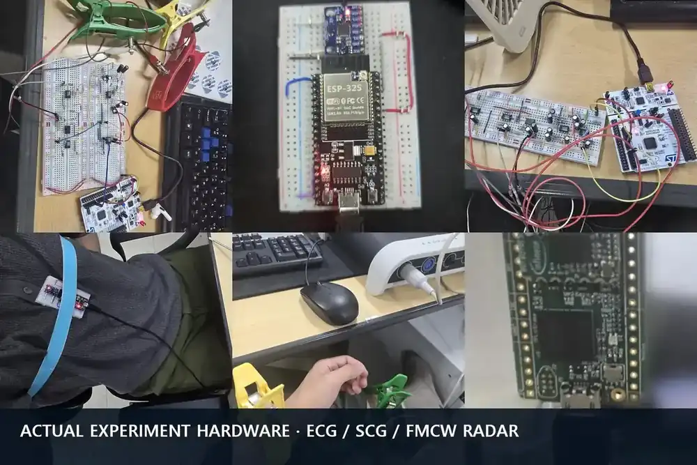
How mmWave Radar Reads Range
I begin with the frequency difference between transmitted and reflected chirps, then separate range, velocity, and angle dimensions.
Engineering Study Track
I connect FMCW chirps, I/Q, range processing, TI people tracking, and research ECG/SCG alignment one step at a time.
I excluded the transcript and third-party paper figure. TI documents are referenced by official URL and my own workflow diagrams rather than copied figures.
8 Topics
I begin with the frequency difference between transmitted and reflected chirps, then separate range, velocity, and angle dimensions.
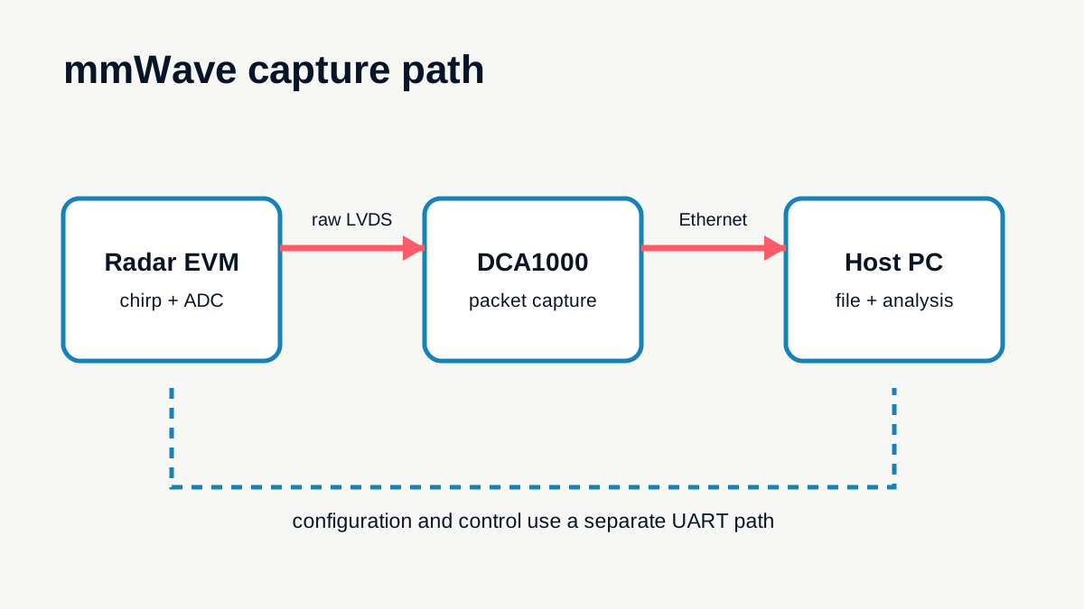
Instead of republishing guide captures, I redrew the roles of the EVM, control UART, raw LVDS, DCA1000, and host, keeping functional and raw-capture modes separate.
I arrange complex I/Q samples by chirp and follow windowing and FFT into range bins without equating every peak with a person.
I separate slow-time FFT for velocity from inter-antenna phase for angle and write tensor axes before processing frames, chirps, and samples.
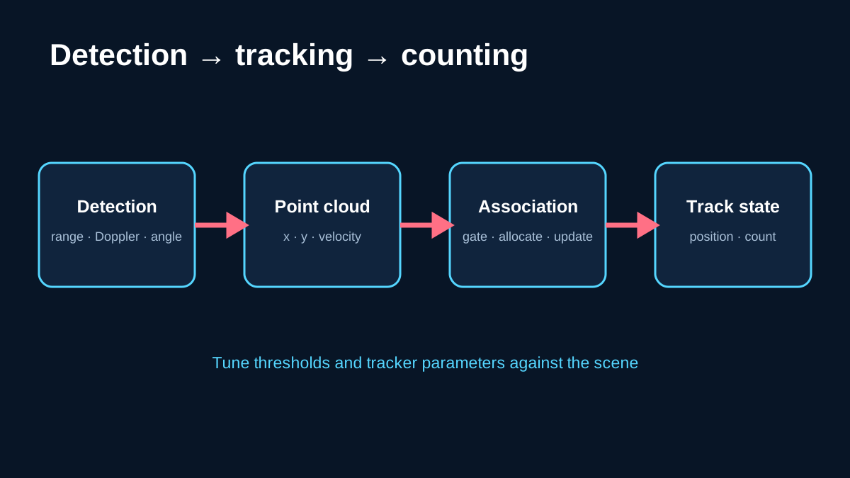
Using the TI reference design, I redraw detection, point clouds, association, track state, and counting. This is preparation for the official demo, not a claimed local run.
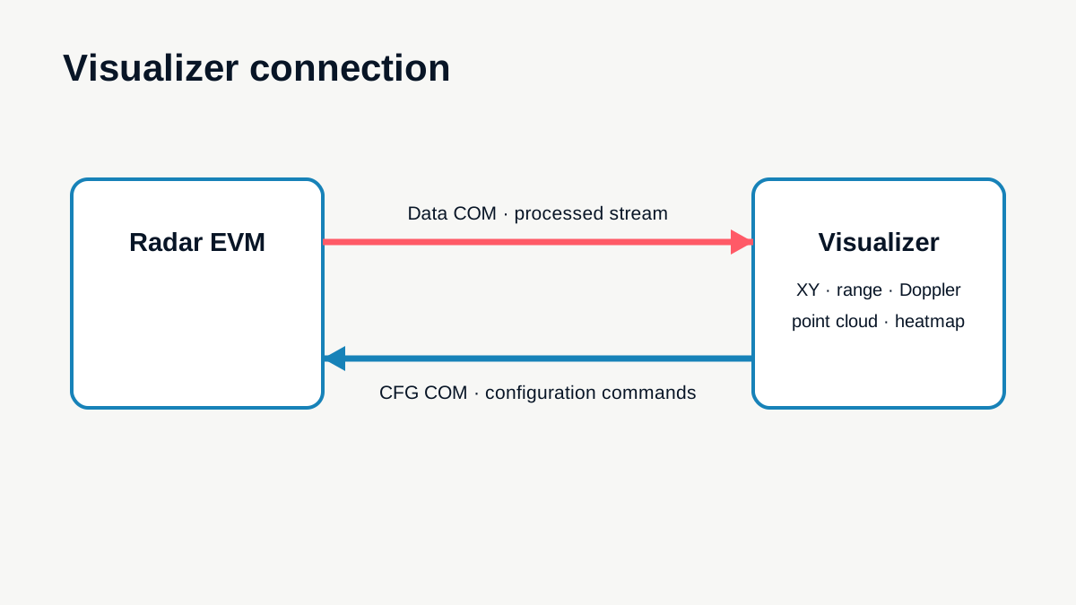
I separate CFG and data ports, configuration transfer, stream reception, and plot reading, without treating the older Demo Visualizer as identical to the current Industrial Visualizer.
I unwrap complex phase at a selected range bin and separate slow motion, keeping respiratory and cardiac interpretation tied to acquisition conditions and reference signals.
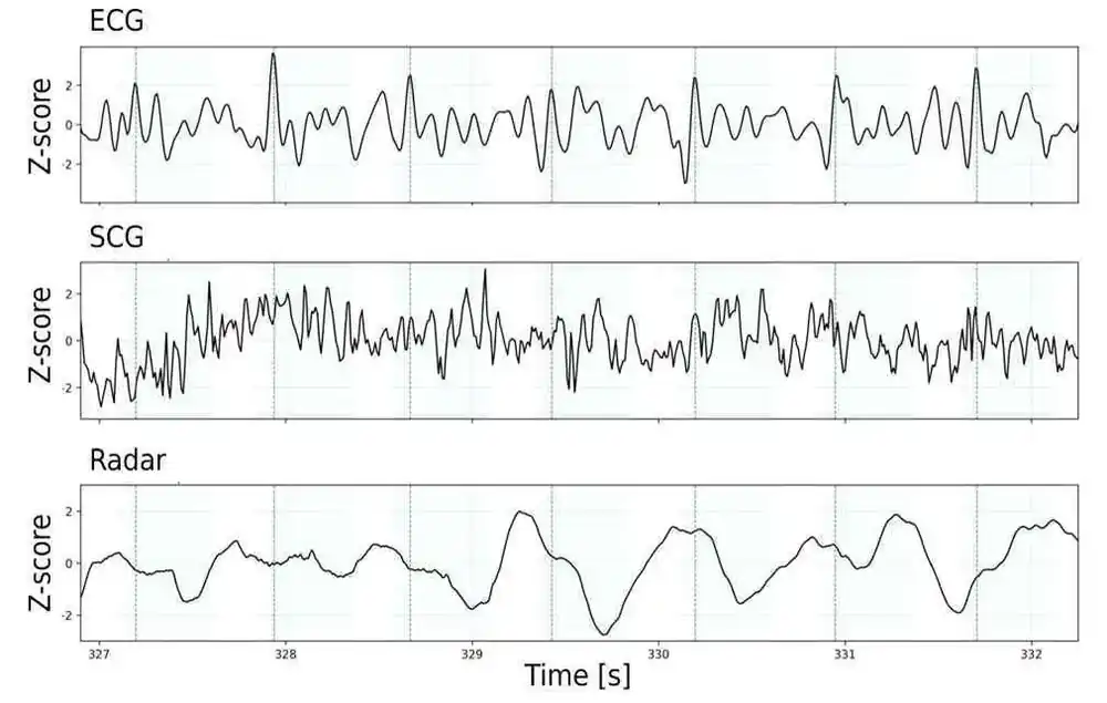
I segment SCG and radar candidates around ECG R-peaks, using AO and AC labels only when concurrent acquisition and annotation conditions support them.