Week 07
Amplifier Frequency Response
I study differential stages, feedback, filters, and output stages as one connected signal path.
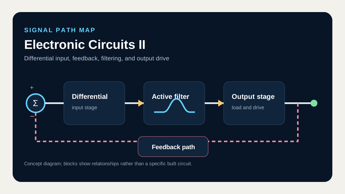
What I connect in this unit
Coupling and bypass capacitors create low-frequency poles, while internal transistor capacitances create high-frequency poles. The Miller effect multiplies a feedback capacitance by gain and can lower the upper cutoff seen on a Bode plot.
Concept map
- Low-frequency poles
- Miller effect
- High-frequency poles
- Bode plots
Technical anchor
For inverting gain Av, the input Miller capacitance is Cin,M ≈ Cμ(1 − Av), and each first-order pole adds another −20 dB/dec magnitude slope.
How I review it
Find the resistance seen by each low-frequency capacitor and the equivalent capacitance at each high-frequency node, order the poles, and mark Bode corners and slopes.
Connection to the full course
Unit 7 of 12. Unit numbers follow concept dependencies rather than the historical lecture calendar.