Week 07
BJT Small-Signal Models
I organize a study path from diodes to single-transistor amplifiers in the order that makes the circuit behavior easiest to revisit.
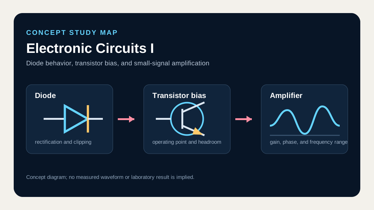
What I connect in this unit
Linearizing the transistor around its quiescent point yields transconductance gm, and the hybrid-pi model gives rπ = β/gm at the input. Including ro at the collector lets one circuit represent gain plus input and output resistance.
Concept map
- Transconductance
- Input resistance
- Output resistance
- Hybrid-pi model
Technical anchor
With gm = IC/VT and the emitter at AC ground, the basic voltage gain is Av ≈ −gm(RC ∥ ro ∥ RL).
How I review it
Use the DC bias current to calculate gm and rπ, then recompute gain from the complete small-signal equivalent including source resistance and load.
Connection to the full course
Unit 7 of 12. Unit numbers form a concept-study sequence and do not claim the original class schedule.