Electrical Engineering Coursework · Motor Control
Cascaded PI Control and Field Weakening for a DC Motor in PSIM
2026-08-01 · updated 2026-08-01 · Hyeongrok Ryu
My study note on the H-bridge, nested current and speed loops, and switching-frequency comparison in an archived motor-control report.
- Series
- DC Motor Control · 1
- Type / level
- study-note · intermediate
- Tools
- PSIM, MATLAB, PI Control
Start with the motor and H-bridge
I first reread the DC motor as coupled electrical and mechanical systems. The armature resistance and inductance sit with back EMF on the electrical side, while inertia, friction, and load torque form the mechanical side. The H-bridge supplies positive or negative average voltage to this plant. I start with a fixed-field operating point, where K_e and K_t can be treated as constants.
vₐ = Rₐiₐ + Lₐ(diₐ/dt) + KₑωJ(dω/dt) = Kₜiₐ − Bω − Tₗ
Current creates torque, and speed feeds back through back EMF. This coupling explains why I should regulate current before asking the slower speed loop to command the plant.
Why I separated two loops
The outer speed PI turns speed error into a current reference. The inner current PI tracks that reference and produces a voltage or duty command. With a faster current loop, the speed loop can treat the inner path approximately as a responsive torque source.
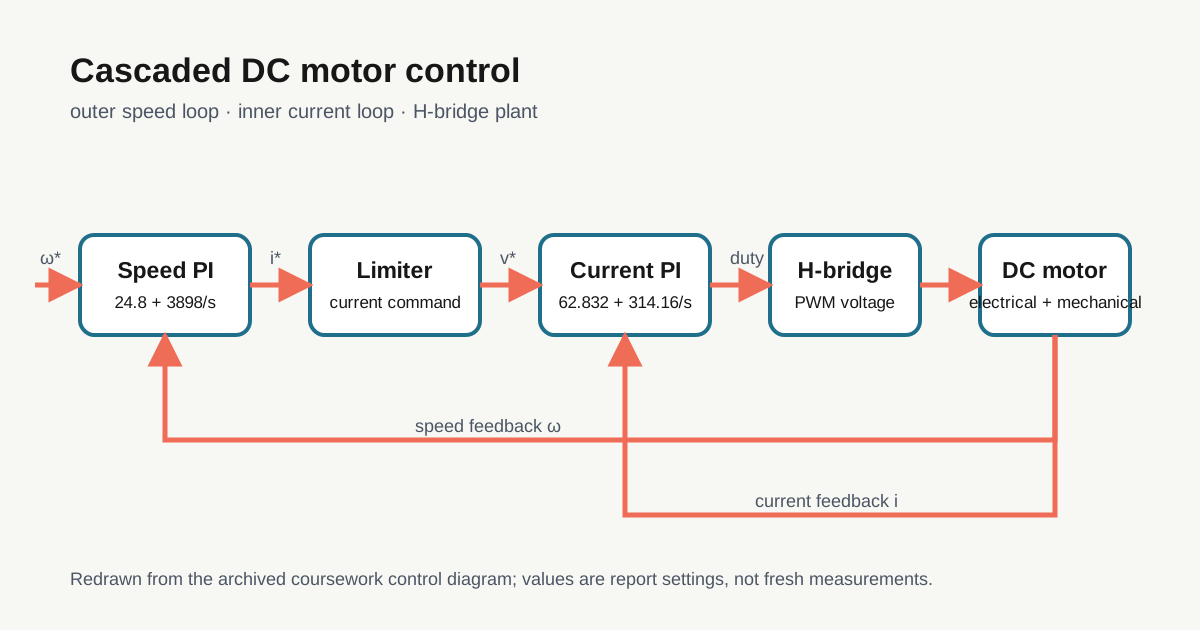
I initially mixed up the two error signals. Writing units beside each block made the roles clear: the speed controller outputs current, while the current controller outputs voltage or duty.
Reading the saved PI settings
The archived report records Kp = 24.8, Ki ≈ 3898 for the speed PI and Kp = 62.832, Ki = 314.16 for the current PI. I treat these as settings tied to that motor model and target bandwidth, not universal optimal gains.
1. Check every motor parameter and unit.
2. Close and test the current loop first.
3. Confirm the current limiter.
4. Close the speed loop afterward.
5. Record saturation and anti-windup behavior.
Saturation and field weakening
Back EMF grows with speed. Eventually the DC bus cannot provide more voltage to maintain the requested current. In the separately excited DC motor used by the assignment, field weakening increases resistance in the field-current path, reducing field current and flux Φ.
Kₑ = kₑΦ, Kₜ = kₜΦ
Reducing flux lowers back EMF at a given speed and leaves room to run faster, but armature current must rise to preserve the same torque. The constant-K_e, constant-K_t model from the first section therefore does not apply unchanged in this region. I use Altair’s PSIM material only as general context for nested loops and operation above base speed; the archived assignment report is the source for this DC field-circuit implementation.
Switching-frequency comparison
The report records 2.28 N·m of torque ripple at 10 kHz and 0.38 N·m at 30 kHz. These are saved PSIM simulation values, not measurements from a physical shaft.
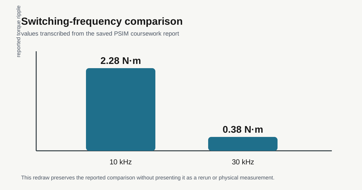
A higher switching frequency can reduce the current change per switching period, but it can also increase switching loss, EMI, and computation demand. I therefore keep this as a one-metric simulation comparison.
Scope of this note
Sources: the archived PSIM model, gains, plots, and a redrawn control diagram. Follow-up experiments: current-loop step response and matched-condition saturation/anti-windup comparisons.
Sources used
- Motor-control coursework report — private-coursework-report; motor parameters, controller settings, and saved simulation comparison
- Altair PSIM Motor Control Design Suite Tutorial — official-documentation; cascaded control and field-weakening context