Electrical Engineering Coursework · Embedded Systems
Sensor-to-alarm data path in a two-node Raspberry Pi drowsiness monitor
2026-07-31 · updated 2026-08-01 · Hyeongrok Ryu
My map of the PPG node, camera/EAR node, TCP/IP, file IPC, GPIO, I2C LCD, and alarm paths.
- Type / level
- project-log · intermediate
- Tools
- C, C++, OpenCV, TCP/IP, GPIO, I2C
Why use two nodes
PPG acquisition and camera-based EAR processing have different timing and compute loads. Running both on one Raspberry Pi can let frame processing interfere with sensor reads and alarm timing. This prototype separates sensing and analysis, transferring state through the network and file IPC.
The split does not prove better performance. It makes each input, stored state, packet, and output boundary inspectable.
PPG and camera nodes
The PPG sensing node reads samples and produces a physiological state. The camera/EAR node processes frames and calculates an eye-state signal. Public C/C++ source and architecture documentation support the existence of both paths.
The decision path combines the two states before driving alarms. A photograph cannot recover thresholds or accuracy, so module boundaries from source remain separate from wiring and assembly evidence.
Packet, file, GPIO, and I2C path
PPG sensor → sensing process → TCP/IP or shared file state
camera → frame processing → EAR state
PPG state + EAR state → decision path
decision → GPIO LED/buzzer + I2C LCD
A reproducible TCP/IP boundary needs message length, reconnect policy, and sender/receiver roles. File IPC needs protection against a consumer reading a partially written file, such as an atomic rename or explicit ready flag. GPIO needs active-level documentation; I2C needs the LCD address and error handling.
Source paths: network, file IPC, GPIO, and I²C. Recovery evaluation requires packet schemas, timeouts, packet-loss handling, and stale-file cleanup conditions.
What the prototype proves

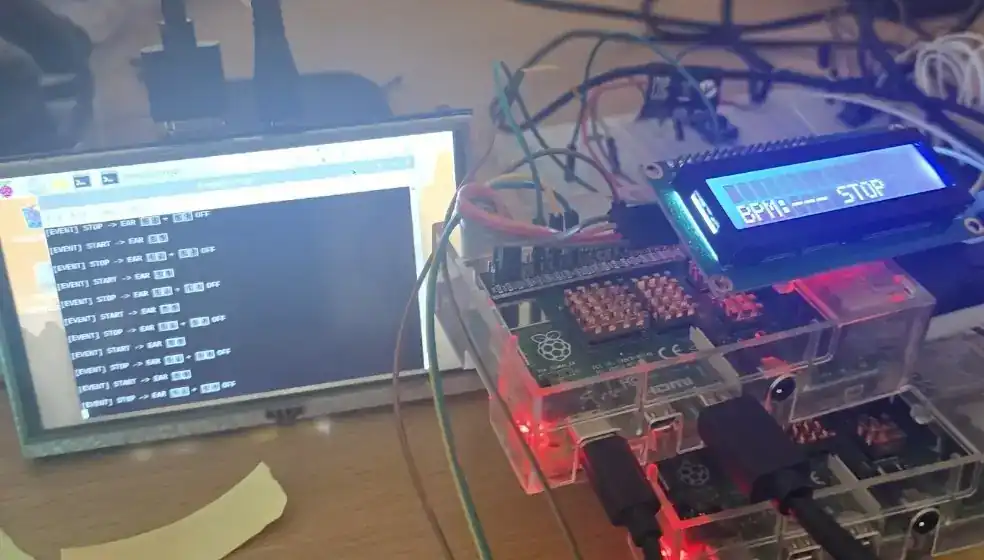
Raspberry Pi, LCD, sensor-wiring, and assembly photographs align with the PPG-server and image/EAR modules to show the two-node data path. Displayed values are prototype outputs.
Failures and unmeasured items
A two-node design must handle missing frames, dropped TCP connections, stale file state, failed I2C writes, and sensor timeouts. The public material does not verify every retry and fallback path.
Prototype records: hardware photographs, PPG server, image/EAR modules, and alarm paths. Follow-up measurements: end-to-end latency, sensitivity, specificity, false-alarm rate, and long-duration stability.
Next verification
The next useful step is a fixed message schema with monotonic timestamps and a shared event ID in both node logs. Fault injection should disconnect the network and stop camera input to confirm that the alarm path moves to a safe state. Until then, prototype existence and performance claims remain separate.
Sources used
- Sleep Monitoring and Prevention Device — public-repository; module and data-path inventory
- Drowsiness Monitor project page — portfolio-page; architecture and next tests