Embedded Systems · Edge Sensing
Real-Time Drowsiness Monitor
PPG와 EAR vision을 두 대의 Raspberry Pi sensing/analysis 구조, TCP/IP, GPIO·I²C alarm path로 통합했습니다.
소스 코드와 실물 프로토타입
01
문제 정의
PPG와 camera 기반 EAR 신호를 분리된 두 Raspberry Pi node에서 취득·분석하고 alarm path로 통합하는 문제입니다.
02
Architecture
PPG sensing node와 image/EAR analysis node를 TCP/IP와 file IPC로 연결하고 GPIO·I²C를 통해 LCD와 alarm 출력을 구성합니다.
03
Hardware · Software
- Raspberry Pi
- C/C++
- OpenCV
- TCP/IP
- GPIO
- I²C
- LCD
04
Data Flow
PPG·camera sensing → node별 preprocessing → network/file IPC → fatigue decision path → LCD·alarm output.
05
Methodology
- PPG server와 image/EAR processing module 통합
- Two-node communication과 상태 전달 경로 문서화
- LCD·alarm interface와 prototype wiring 정리
06
Results
- C/C++ source에 구현된 two-node architecture
- TCP/IP·GPIO·I²C가 잇는 data와 alarm path
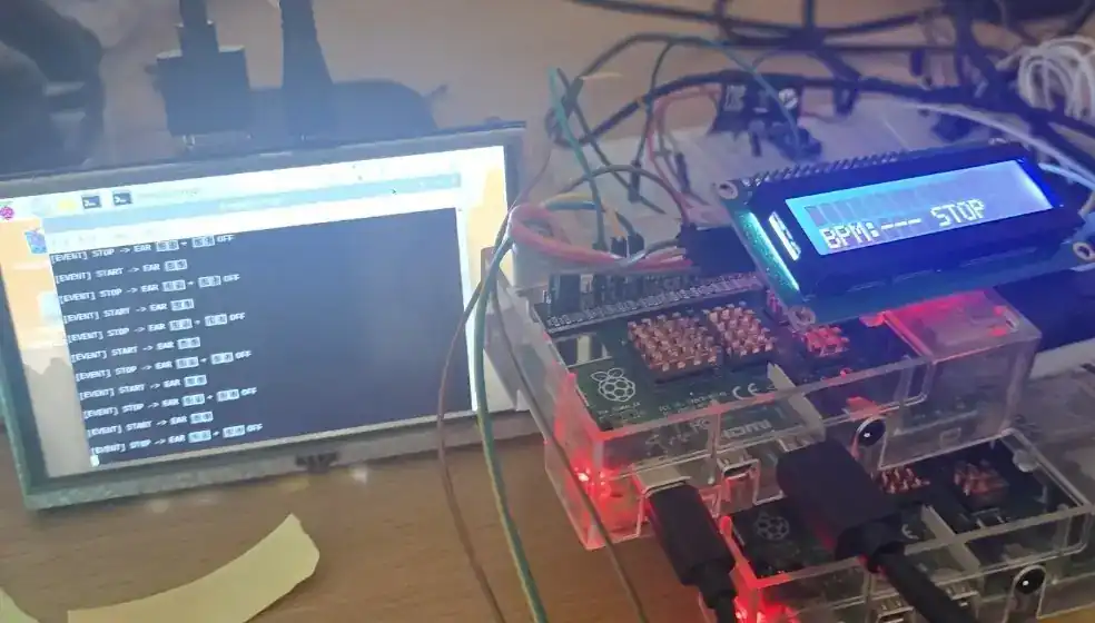
- 당시 prototype 사진에 남아 있는 LCD와 sensor wiring
PPG와 camera 기반 EAR 신호를 분리된 두 Raspberry Pi node에서 취득·분석하고 alarm path로 통합하는 문제입니다.
PPG sensing node와 image/EAR analysis node를 TCP/IP와 file IPC로 연결하고 GPIO·I²C를 통해 LCD와 alarm 출력을 구성합니다.
PPG server와 image/EAR processing module 통합
C/C++ source에 구현된 two-node architecture
구조와 결과 화면
내가 맡은 부분
- PPG server와 image/EAR processing
- Two-node file IPC·network architecture
- LCD·alarm integration path 문서화
코드와 결과
- C/C++ source와 architecture 문서
- 회로·LCD·prototype 사진
- TCP/IP, GPIO, I²C data and alarm paths
남은 과제
다음에는 latency, sensitivity, specificity와 false-alarm rate를 같은 실험 조건에서 측정해 수치로 비교할 계획입니다.
프로젝트 자료
실제 prototype 사진은 구현과 통합 경로의 존재를 보여주지만 정확도, 지연시간, 민감도 또는 오경보율을 대신하지 않습니다.